


In this KiCad activity, you will draw the schematic for a PCB of an LED light sensor. You may find our write-up on KiCad schematics, the reading for this week, a helpful reference. We also recommend using a mouse for all labs as it will make navigation and component placement much easier.
KiCad Setup
Follow the instructions in Install KiCad
Ask for help if you run into any issues.
Getting Started
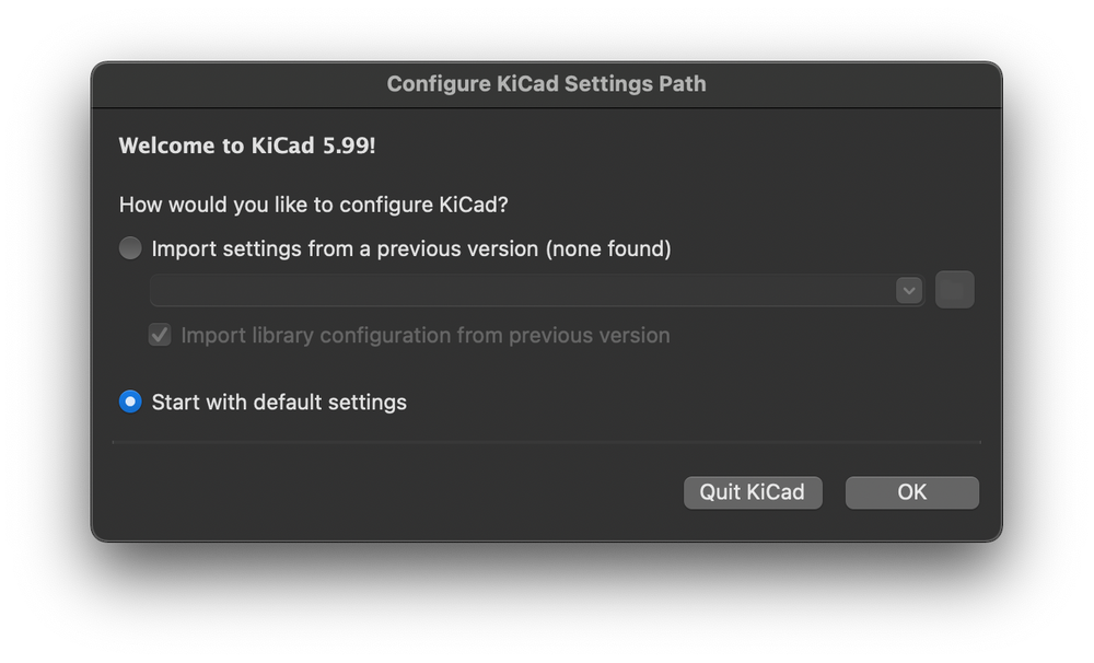
- Launch KiCad. You should be greeted with the main project manager window. Note: Click
OKif you see a dialog box similar to the one below (with default settings selected):
-
Make a new project by
File -> New -> Projector by using the keyboard shortcutCtrl-N. Pick a reasonable project name (i.e. light sensor) and a safe place to save your project directory (a folder will be created to house all your KiCad project files)You won't be able use KiCad (or any other PCB ECAD for that matter) as a comprehesive PCB ECAD unless you're working under the context of a project, so make sure to do this step!
Schematic Capture
Open the 'Schematic Editor'. Click OK if you see the following dialog box (with the recommended option selected):
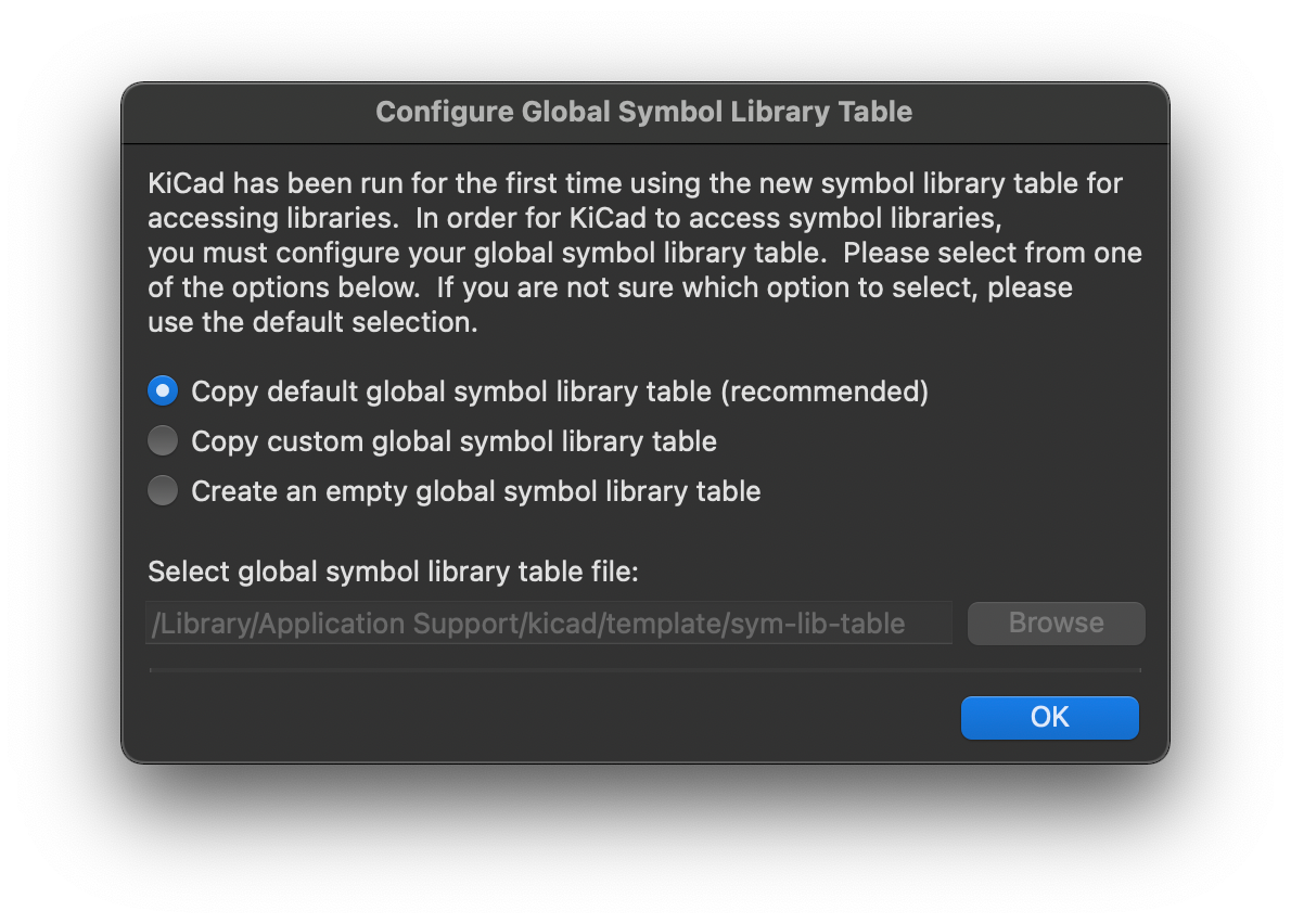
In case the first option is greyed out, please ask an instructor for assistance.
Your goal is to replicate the KiCad schematic shown below:
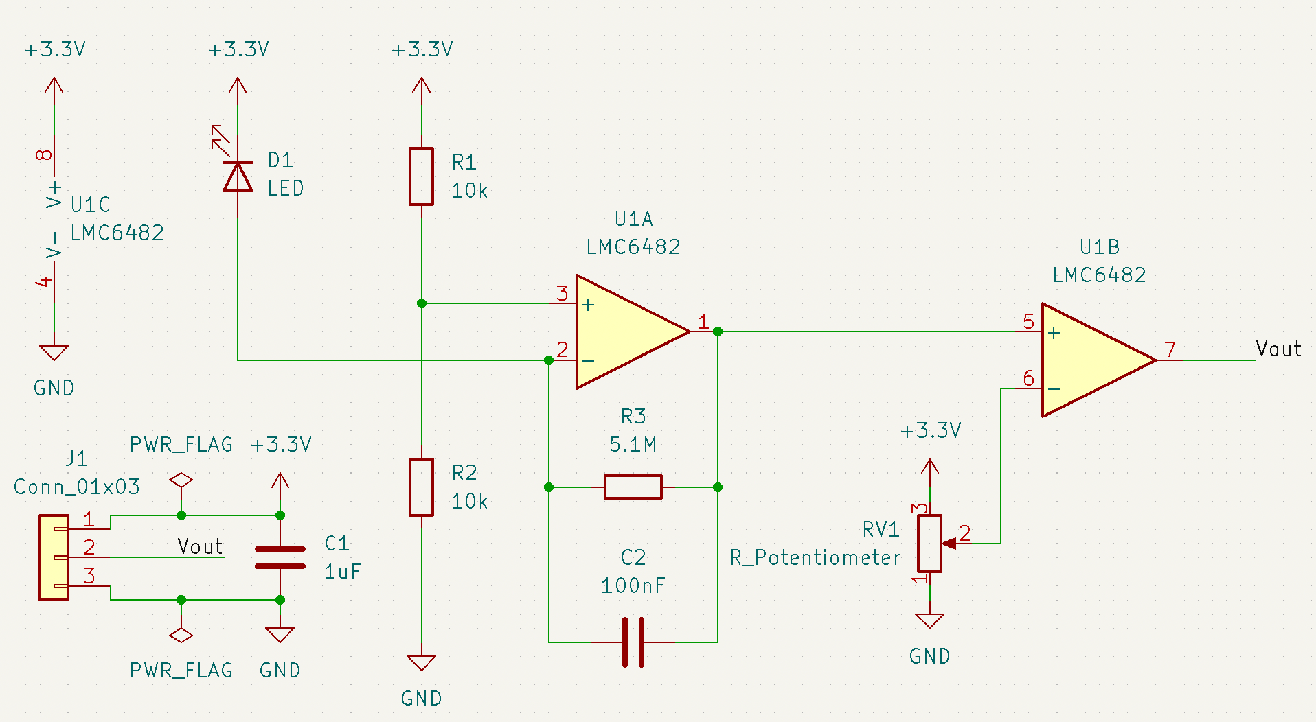
-
The first thing we want to do in the schematic is to add the op-amp. Press the 'a' hotkey to add a symbol, click anywhere to place a symbol, and press 'Esc' to stop adding symbols.
Interested in why the op-amps come as these separate units of one part? Take a look at page 18 of the LMC6482's datasheet to get some idea of why the component would be set up this way.
Go to
Help -> List Hotkeys... or pressCtrl+F1(Win)Cmd+F1(Mac) to open up KiCad's built-in keyboard shortcuts cheat sheet! Note that the middle mouse can be used to drag your view in both the schematic and layout editor. This will help alleviate the headache of trying to scroll around both.
-
Continue by placing the following parts to match the completed reference schematic:
-
2 capacitors (
CorC_Small) -
3 resistors (
RorR_Small) -
a LED part symbol (
LED) -
a potentiometer part symbol (
R_Potentiometer) -
a 1×3 connector part symbol (
CONN_01x03) - should be listed as generic
-
-
After placing the symbols, notice that the reference designators (ie. R1, R2, C1, C2, U1...) are blank (R?, C?, U?A etc..). This is ok! Leave them as is for now as they will be auto-populated later.
-
The values for the resistors and capacitors will also be blank (R, C), ignore this for now
-
Wire up your components! Press the 'w' key to activate the wire tool and press 'Esc' to go back to the selection tool. Repeat until the schematic is fully captured.
-
Drag placed wires by selecting or hovering over them and pressing 'g'. Delete segments by selecting or hovering over and pressing 'Backspace' or 'Del', or right-click the wire for more options.
-
To create a wire that does not connect to a component on one end
(floating wire), double-click where you want the wire to end. Floating wires will be useful for components that will need power or ground labels later. -
To add labels (the 'Vout' label shown above), press 'L' and type in the
name of your label. Labels connect two or more nodes together without
actually drawing the wire on screen. They are basically magic wire tunnels
linked by name. -
Note that these wires do not stay snapped to component pins. If you move or rotate a component, its seemingly connected wires will not follow.
-
-
Now add power symbols to your schematic. For this step, it may be easier to duplicate a component instead of adding multiple of the same component. To do this, select the component you want to copy and press 'Ctrl+C' ('Cmd+C' for Mac). Paste with 'Ctrl+V' ('Cmd+V').
-
Next, add power flags to the schematic. Just like the power symbols it may help to duplicate a component: 'Ctrl+C' ('Cmd+C' for Mac). Paste with 'Ctrl+V' ('Cmd+V').
Power flags serve to tell the Electrical Rules Checker(ERC) in subsequent steps that the pin or wire is connected to power even if a power source isn't specified.
-
Assign values to components. The easiest way to do this is to select or hover over the component and press 'V'. You can also double-click the component to open its properties or right-click and open 'Properties'. Type the appropriate value. Omit units for resistors but include units for capacitors and inductors (F for farads, H for Henries, etc.). For example, a 1kΩ resistor value would simply be
1kand a 1 nF capacitor value would be1nF. -
Annotate your schematic, this assigns a unique reference designator (ie. R1, U1, C1, etc.) to each component. You can manually do this for each component by using the right-click 'Properties' menu, but we suggest doing this automatically by using
Tools → Annotate Schematic → Annotate.
You can also click this icon:
Feel free to use these interface menus to learn more about KiCad's functions, or even for this entire first lab. However, we do recommend learning how to use the keyboard shortcuts, as doing so will speed up your work in future projects considerably. Also, you'll look much cooler.
-
Run the Electrical Rules Checker (ERC) and ensure there are no errors. If there are, fix the listed errors in your schematic and run the ERC again, until it is error-free.
Click this icon to run the ERC:
-
Visually double-check your schematic to make sure it matches the reference schematic above. The ERC does not check this for you.
Check-In
A checkoff is not needed after you complete this portion. However, we highly recommend you check in with an instructor if you have any questions about your schematic.
Do remember that this part will need to be completed before you can move on to the next section of this lab, which will be graded.
You may preview Week 2's lab on layout.