


- Turn on the soldering iron and wet the sponge -- you'll be using the sponge to remove excess solder from the soldering iron while soldering.
- Wait 1~2 minutes for the iron to heat up, and clean off excess solder by wiping it on the sponge.
- “Tin the iron” by touching the iron with solder. The solder should melt instantly and cover the tip with a protective layer that improves the iron’s ability to transfer heat. As you’re soldering, make sure that the tip is always shiny. If it is not, you can tin the iron again.
- Insert a part through the through-holes. Hold the iron to the joint, heading up both the lead and the copper pad on the board. Bring the tip of the solder wire and press it gently onto the now-heated copper pad. The solder should melt and connect the lead to the copper pad. Note: Do not heat the solder and bring the melted solder onto the pad -- this creates an unreliable connection.
TODO: add images from doc to here about sponge/iron

If done correctly, you should be able to see the solder "cling" to the pad and the component, as shown in the pictures below:

TODO: add another image? (there used to be 2)
If you have created a bad joint, you can re-heat the joint and let the solder flow onto the pad. A list of common problems and their fixes can be found here: https://learn.adafruit.com/adafruit-guide-excellent-soldering/common-problems
If there is excess solder on the board (e.g., a solder bridge, shown on the right image below), you can remove the excess solder with a solder pump.

Assemble PCB
Once you’re ready to solder, it’s time to assemble your printed circuit board (PCB), which connects the electrical components on our mouse together. Here’s what it’ll look like when you’re done:
TODO: add image of Micromouse
Note: You need to solder the female headers to the board (below, the ones that have wires only on one side). You solder the male headers (with wires on both ends) to the Arduino and motor driver. This makes it easy to remove either of them for reuse later.
DO NOT SOLDER THE ARDUINO DIRECTLY TO THE PCB!!!
TODO: add image of Micromouse, labeled parts
Solder each component on, paying extra attention to the color of the resistors and direction of the LEDs. Typically the flat side of the LEDs should face away from the button, but our LEDs actually don’t have a flat side. We can instead look for the side with the shorter leg. This side is the negative side, which is where the flat side would be (you can also refer to the LED cross section below).
TODO: add first image of LED directions
TODO: add second image of LED directions
Tips:
- You'll have to cut the headers to the right length
- To make sure the headers for the various modules on the board are aligned, you should insert the module into the headers before soldering.
TODO: image of arduino
TODO: close up of completed robot
TODO: close up of clamped motor
TODO: top view of PCB
TODO: side view of PCB
Checkoff #1
- Show your mentor your assembled PCB!
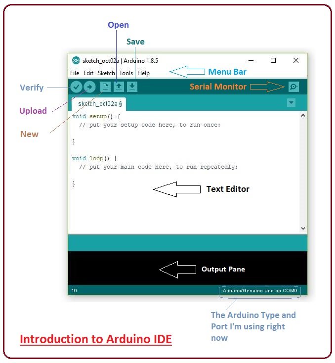
We’ll be using the Arduino IDE to program our mouse:https://www.arduino.cc/en/Main/Software
Setup
- You might need to install CH340 Drivers: https://learn.sparkfun.com/tutorials/how-to-install-ch340-drivers/all
- Pick your board type: Tools >> Board >> Arduino Uno
- Pick your port: Tools >> Port >> [Correct COM Port]
Things you care about:
- Upload button (➔): sends code to Arduino
setup()method: everything in here runs once at the beginningloop()method: everything in here runs continuously after setup
Let’s first start with an example:
#define PIN_LED1 A2
#define PIN_LED2 A3
#define PIN_BUTTON A1

void setup() {
	// Set the LED pin as an output
	// This lets us "write" the voltage
	pinMode(PIN_LED1, OUTPUT);
}

void loop() {
	// Turn the LED on
	digitalWrite(PIN_LED1, HIGH);

	// Wait one second
	delay(1000);

	// Turn the LED off
	digitalWrite(PIN_LED1, LOW);

	// Wait one second
	delay(1000);
}
What does this do?
(1) It defines which pins the LEDs are connecting to. We want the microcontroller to know which pins are LEDs. (2) It sets up the pins. n our setup() method, we use a function called pinModede. This method lets us set a pin to either INPUT (read) or OUTPUT (write) mode. Since we want to output something to our LED pin, we pick OUTPUT. (3) It writes to the pins. Here is where we tell the LEDs what to do. We use the method digitalWrite() that takes in the pin number and writes HIGH or LOW to it. HIGH indicates the LED is on and LOW indicates the LED is off. In the example blink LED1.
Checkoff #2
- Demonstrate this blink code working on your arduino.
- What is the purpose of the
setup()method, when would you put code in here? - What is the purpose of the
loop()method, when would you put code in here?
Then lets see a bit more syntax:
#define PIN_LED1 A2
#define PIN_LED2 A3
#define PIN_BUTTON A1

//How to set up a global variable, and initialize it with a value
int counter = 0;

void setup() {
	// Set the LED pin as an output
	// This lets us "write" the voltage
	pinMode(PIN_LED1, OUTPUT);
}

void loop() {
	counter++;
    //Modulus Operator Ex. 12 % 10 = (remainder of 12/10) = 2
	if (counter % 10 == 0) {
  		// Turn the LED on
  		digitalWrite(PIN_LED1, HIGH);
  		// Wait one second
  		delay(1000);
  		// Turn the LED off
		digitalWrite(PIN_LED1, LOW);
	}
	// Wait 300 milliseconds
	delay(300);
}
What does this do?
(1) If statements are used to make a decision based off some parameter, called a conditional. We’re using ours to decide to turn the light on. (2) Our counter variable is just an ordinary variable, but we can use it to perform certain chunks of code at different time intervals(or number of loops). For example checking the status of a certain sensor every 10 loops.
Checkoff #3
- What does counter++ do?
- After the LED turns off how long will it be until it turns back on? Quickly explain your answer.
- Name another conditional used in programming besides the IF statement.
Here we’ll use analogRead() method to see whether the button on your PCB is pressed or not. Fill in approximately 4 spots to have your Arduino turn on a LED if the button on your pcb is pressed.
#define PIN_LED1 A2
#define PIN_LED2 A3
#define PIN_BUTTON A1

void setup() {
	// Set the LED pin as an output
	// This lets us "write" the voltage
	pinMode(___________________, OUTPUT);

	// initialize the pushbutton pin as an input:
	pinMode(___________________, INPUT_PULLUP);
}

void loop() {
	// read the state of the pushbutton value:
	int buttonState = analogRead(PIN_BUTTON);

	// check if the pushbutton is pressed.
	// if it is, the buttonState is HIGH:
	if (buttonState > 50   ) {
		// turn LED on:

	} else {
		// turn LED off:

	}
}
What does this do?
digitalRead() allows us to check the voltage on a certain pin, assigning the digitalRead() a 1 if there is a positive voltage on the certain pin, and assign it a 0 if the Arduino does not detect a positive voltage on the pin. Pressing the button assigns the A1 a positive voltage.
Checkoff #4
- Demonstrate your push button code working.
First, we’ll get you acquainted with all the parts in your box (let us know if you’re missing any parts). You’ll get to learn even more about each of these specific parts throughout the course.
Your beautifully soldered PCB
TODO: Add picture!
Motors (x2): These motors will be used to move the car wheels. They take electrical signals from the microcontroller which tell it which direction and how fast to move, and they send small pulses back to the microcontroller to show how much distance it’s moved so far (more on this in Lab 2)
TODO: Add picture!
Wheels × 2: It’s a wheel. From the free Encyclopedia: In its primitive form, a wheel is a circular block of a hard and durable material at whose center has been bored a circular hole through which is placed an axle bearing about which the wheel rotates when a moment is applied by gravity or torque to the wheel about its axis, thereby making together one of the six simple machines.
USB A to USB B cable × 1
TODO: Add picture!
5-pin Female - Female connector (x1): You’ll hear these descriptors “male” and “female” a lot. Male header pins are easier to solder, but for less permanent connections we attach them to a female header pin.
TODO: Add picture!
Snap-type battery connector (x1): This will be used to connect a battery (which “snaps” on) to your car to power it.
TODO: Add picture!