


Motors and PID
Last time we learned how to measure how fast our mouse is moving and turning. This week we'll use these values to make our mouse drive straight!
Brushed Motor Control
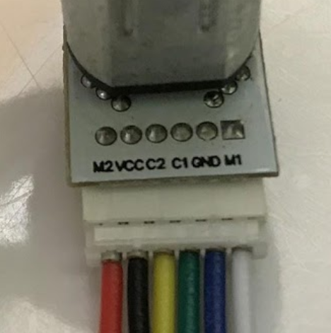
In addition to the encoder pins we've seen in the previous labs, the M1 and M2 pins power the motor itself. Applying a voltage across them makes the motor spin in one direction. Reversing this voltage makes the motor spin in the other direction.
Motors need large amounts of current and as such our Arduino can't drive them directly from its IO like we could with the LEDs. To solve this problem, we use the DRV8833 motor driver chip. It can drive two small motors and includes features like overcurrent protection and PWM control.
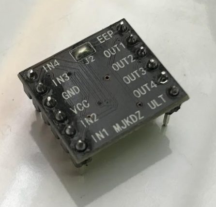
Above is the DRV8833 breakout board we use in our Micromouse. One of the motors is connected to the OUT1 and OUT2 pins while the other is connected to the OUT3 and OUT4 pins. The Arduino is connected to the INx pins to allow it to control the corresponding OUTx pins.
Since the DRV8833 is a high power device, it needs to be powered off the 9V lithium battery included in your Micromouse. When using the motors, plug in the battery. It should be safe to plug both the battery and the USB in at the same time.
You may have noticed that the motors can move even when the battery isn't plugged in, albeit at a lower speed. This is unintended behavior as the 5V from the USB goes backwards through the voltage regulator and powers the DRV8833. The Arduino's we use are clones, but they should have the protections necessary to ensure this behavior doesn't damage anything.
Now let's get to the code. Copy over the following starter code and read the following section for help with the TODOs.
To control the motors, we can reference the datasheet. The relevant section is copied below for convenience.
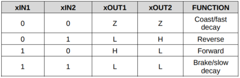
"1" means setting a pin to HIGH while "0" means setting it to LOW. "Z" means the pin is "disconnected" which is also known as high impedance mode. Since we power the DRV8833 with 9V, "H" means 9V and "L" means 0V.
Based on the datasheet, we can try a couple different things. What will the following code placed in loop() do? What if we wanted to try the other direction?
What if we want to stop? We just set both pins to the same value. There's two ways to do this. What's the difference?
What if we want to spin the motor at a different speed? So far we've only been able to run the motor at full speed or stop. We can switch between these two states really fast so that we average out to some place in between. This is the basic idea behind PWM.
Arduino has a builtin function for this: analogWrite(). It takes in a pin and value from 0-255. As usual, it abstracts out the complexity of setting up the registers to achieve a certain frequency and phase alignment. A value of 0 corresponds to the pin being HIGH 0% of the time while a value of 255 has the pin HIGH 100% of the time. A value in between has the pin HIGH some other % of the time. The following code should make the motor spin slowly.
Notice that we run analogWrite() on one pin while keeping the other pin HIGH. This makes us switch between the brake state and either forward or reverse state quickly. If you're curious, check out this video to learn why we don't switch to the coast state instead. Basically, it improves efficiency and reduces inductive kickback.
Checkoff #1
- Demonstrate your working code.
- What's the difference between setting both motor pins HIGH and setting both LOW?
- How do you change the speed of the motor?
- How do you change the direction of the motor?
Some Setup
At this point, the skeleton code is getting a little long to just copy paste so we've thrown it onto Github. It provides easy to use functions for everything you've done so far. Arduino is a bit strange in that it requires the main sketch (mouse.ino) to be in a folder of the same name (mouse/). If you download the zip from Github, make sure to rename your folder. If you want to do a git clone instead, try the following.
Open up mouse.ino in the mouse/ folder. If you look at loop(), by default the code will apply 20% power to each motor. applyPowerLeft() and applyPowerRight() are intended to drive their corresponding motors full speed forwards when given 1.0 and full speed backwards when given -1.0.
Upload and run the code and do the following:
- Verify that each wheel is physically spinning in the forward direction (ToF sensors are the front of the mouse). If not, flip the INVERT_MOTOR_LEFT and INVERT_MOTOR_RIGHT flags as needed.
- Verify that the measured linear velocity is positive. If not, flip the INVERT_ENCODER_LEFT and INVERT_ENCODER_RIGHT flags as needed.
- Update WHEELBASE_DIAMETER and ENCODER_TICKS_PER_REVOLUTION on lines 109 and 110 in mouse_helpers.ino, using values from the last lab.
Checkoff #2
- Show that your motors spin forward and the measured velocity is positive.
Driving Straight (Angular Velocity Control)
The default code is an example of open-loop control where we apply some input and hope we get our desired output. In this case, we want to drive straight but you may have noticed that the mouse doesn't drive completely straight even with the same input power to both motors. This is for various reasons, including but not limited to the following:
- The mouse isn't perfectly balanced as all things should be.
- The ground is not perfectly flat.
- Our motors aren't exactly the same. We'd probably violate some quantum physics law.
To fix this, we can apply something called close-loop control. Also known as feedback control, we take measurements from the encoders to adjust the power to our motors and drive straight. For example, if we are veering to the left based on encoder readings, we can increase power to the left motor and decrease power to the right motor to correct it.
One common way to do feedback control is PID. For now, you'll just be implementing just the P part of it. Conceptually, feedback controllers try to minimize some error which is the difference between a measured value (aka process variable) and setpoint.
For our P controller, we vary our motor power proportionally to our error. That is, the larger our error, the more power we apply to correct for it.
$$u(t) = K_p e(t)$$
Let's modify the default code to have a u_angular feedback correction term like follows. It doesn't need to be the same, but this is a good starting point.
Now implement a P controller as described above. \(K_p\) is a constant gain that scales our corrective power. There are ways of optimizing \(K_p\), but manual tuning (try starting at 1) is adequate for our use case. Before starting, ask yourself what the process variable and setpoint are. The corrective force might be being applied in the wrong direction, so swap +/- if your error is blowing up instead of reducing.
Checkoff #3
- Demonstrate your working P controller by opening the Serial Plotter and showing that the angular velocity converges to around 0.
- If we want to drive straight, what's our angular velocity setpoint?
- If we want our applied correction power \(u(t)\) to be maximized (\(u(t) = 1.0)\) when the error is 2 radians/second, what should \(K_p\) be?
- Try a few different \(K_p\) values. \(K_p\in\{0.1,0.5,5\}\) is good. What happens when \(K_p\) is too low? What about too high? What value did you end up using?
Linear Velocity Control
Instead of blindly adding 0.2 to our applied motor power to go forward, what if we also want to control our linear velocity too? We add another P controller!
This allows our mouse to drive forwards and backwards as well as stop. Being able to control the speed of our mouse is really useful. Just as imbalances in the motors can prevent our mouse from driving straight, they can also cause our mouse to drift when turning in place.
Implement a P controller but for linear velocity. If you wrote your angular velocity P controller code well, implementing a P controller for linear velocity should be a straightforward copy, paste, and modify. What's your new process variable? What about setpoint?
When implementing, a setpoint of 700mm/s is a good starting point. Try starting \(K_p\) at 0.1.
Checkoff #4
- Demonstrate your working P controller by opening the Serial Plotter and showing that the linear velocity error converges to around 0 (linear velocity matches target).
- What are the process variable and setpoint of our new controller?
- If we want our applied correction power \(u(t)\) to be maximized (\(u(t) = 1.0)\) when the error is 140mm/s, what should \(K_p\) be?
- Try a few different \(K_p\) values. \(K_p\in\{0.001,0.01,0.1\}\) is good. What happens when \(K_p\) is too low? What about too high? What value did you end up using?