Encoders
When we are navigating the maze, we would like to keep track of a couple things.
- How fast is the mouse going?
- Is it driving straight?
- How far has it driven?
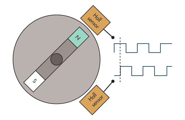
To answer these questions, we'll use the quadrature encoder sensors mounted on the back of your motors. They consist of a spinning magnet and two Hall effect sensors mounted 90° apart. Hall effect sensors measure the presence of magnetic fields. In our case, they output a digital HIGH when closer to a north pole and LOW when closer to a south pole.

Let's try reading from the encoder! Upload the following code.
Now open up the Serial Monitor or Serial Plotter. Spin the left motor by hand using various speeds and note how the printout changes. Note that with just one input, it's impossible to tell which direction the motor is spinning.
Checkoff #1
- What's the output when the motor is stationary?
- What's the output when you spin the motor faster? Why?
- Why do we need two Hall effect sensors per motor?
- Refer to the waveforms above. Which direction is the motor spinning?
Going the Distance
Next let's try tracking the position of your left wheel. We're going to use a technique called polling which we'll go over more in the next section. Fill in the TODO in the following code. Hint: You'll need digitalRead().
After uploading the code, open up the Serial Monitor or Serial Plotter and spin the motor in both directions. The output count should go up and down as you do it!
Checkoff #2
- Roughly how many "ticks" correspond to a revolution? How do you think this is computed?
- What issues might the "polling" method have?
- Now that we can measure position, how might we measure velocity?
- What effect does swapping the A and B pins have on how we measure position?
Polling (aka are we there yet?)
The polling technique involves repeatedly checking a signal to see if it changes. This can be inefficient and even miss edges if the wheel is spinning too quickly. Moreover, constantly having to check a signal takes up a lot of CPU time that could be used for other purposes. While polling is adequate in some cases, for an encoder we need something better.
Interrupts (aka hey kids we're here!)
The interrupt technique basically involves interrupting the CPU when something happens and making it run some code. After running that code, the CPU can resume normal operation from where it was interrupted. In the case of our Arduino, it has specialized hardware to generate an interrupt when an input pin changes state.
As is the theme for Arduino, all of the complexity of setting up interrupts is abstracted away so all you need to do is call one function.
Using interrupts, we can also get an accurate approximation of velocity (in ticks/second) by measuring the time between encoder ticks and taking the reciprocal.
Fill in the TODOs in the following code to reimplement your encoder tick counting from before and also add velocity measurements. Hint: The Arduino micros() function gives us the time elapsed since the code started running. Also keep an eye on the data types of variables and constants you're using (integer division discards the decimal!). Ask your mentor for help!
Checkoff #3
- Show the Serial Plotter output while spinning the motor by hand and have your mentor check that the position and velocity plots look correct.
- Why might we use interrupts over polling?
- If we stop the motor, the velocity will never actually hit zero. How might we fix this?
Aside
- We're using X1 encoding for our encoders, which means we only detect one edge out of four for each cycle. We could use X4 encoding to quadruple our resolution. However, due to cheap construction our encoder's Hall effect sensors aren't spaced a perfect 90° apart which means each tick is not equal in distance.
- Our Arduino only has two dedicated interrupt pins so it's not as easy to do X4 encoding. There is something called a pin change interrupt which is more complex to set up but would make this work.
- Generally speaking, you should avoid using floating point operations (math with decimals) in embedded systems because they're computationally expensive. If you do need them, some microcontrollers like the Cortex M4F or M7 have a dedicated hardware FPU to perform these calculations quickly. However, integer math suffices for most applications. A common trick is multiply your variable by some constant so instead of storing 69.420 in a float you'd store 69420 in an int.
