Introduction
In this 2-part hands-on experience, you will be assembling a version of the microbug and be introduced to a set of common testing and debugging techniques for PCBs with microcontrollers. In today's lab, you will partially assemble the microbug, learn to use some lab equipment and mess around a bit with programming the ATTiny microcontroller.
Prelab
Before you come to the in-person activity, we highly recommend that you set-up the programming tools that you will need for the ATTiny microcontroller and get the starter code.
Programming the microcontroller requires just the Arduino IDE and the megaTinyCore, a "board" library for the Arduino IDE that does most of the hard work for us. We will be programming these ATTinys via a simple USB-to-Serial dongle that will act as a UDPI (Universal Debugging and Programming Interface) programmer.
- Get the latest version of the Arduino IDE here: https://www.arduino.cc/en/software
- Install the megaTinyCore board add-on using the Board Manager (see the “Boards Manager Installation” section) following these instructions: https://github.com/SpenceKonde/megaTinyCore/blob/master/Installation.md
(If you are familiar with how to add boards, the url to add is http://drazzy.com/package_drazzy.com_index.json )

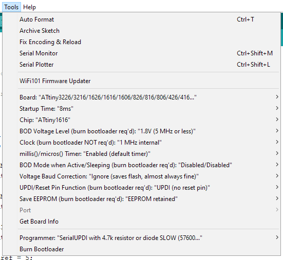
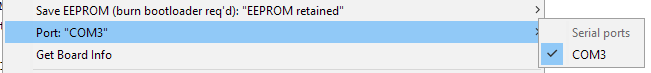
- It is not necessary to do now, but before you program the microbug you will need to change your Tools dropdown to match these settings:
- Download the starter code from this link here: https://github.com/IEEEBerkeley/microbug_fw
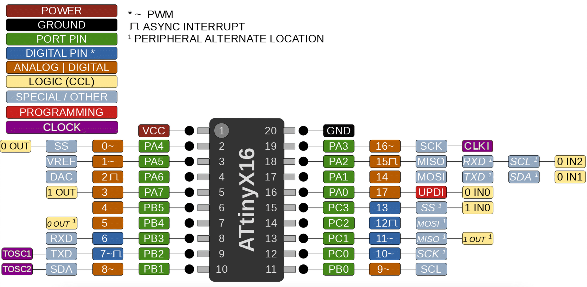
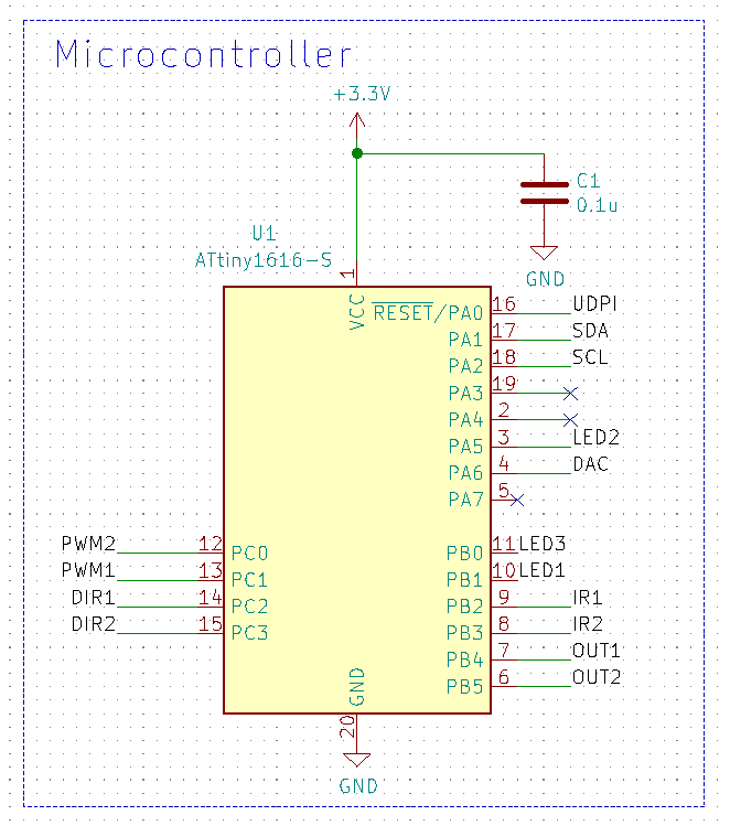
This will have all the pins you’ll need to control predefined and preconfigured for their proper operation. You can look more at this link here for how the pins are mapped in the Arduino IDE and if you want to experiment beyond what we do in this lab: https://github.com/SpenceKonde/megaTinyCore/blob/master/megaavr/extras/ATtiny_x16.md
In-Lab
We have broken up the assembly and test process into a few steps to guide you through the bringup process.
Stage 1
Assembly
You will first need to assemble the following parts in this order:
- Solder MCU (U1)
- Solder resistors (R1, R7)
- Solder LEDs (D1, D3)
- Solder programming resistor (R8) and programming header (J1)
- Solder power header (J2)
- Solder the auxiliary power header (J4)
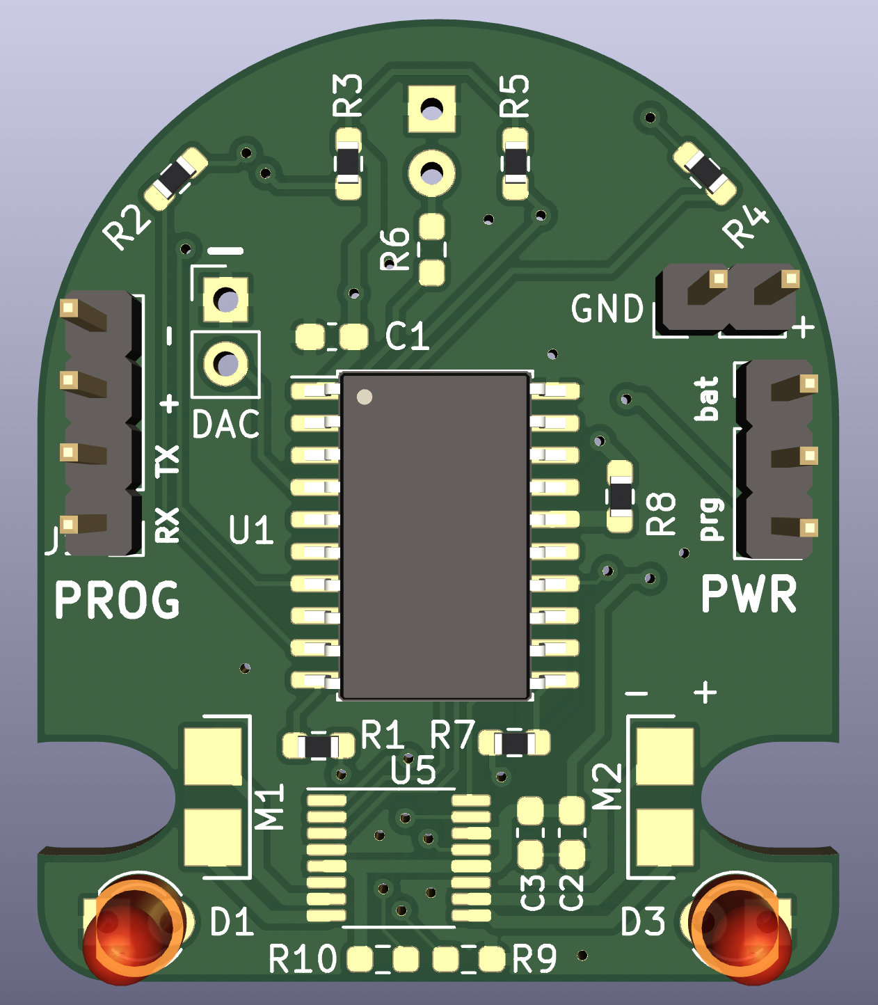
This is what you should expect your board to look like after finishing the first stage:

Testing
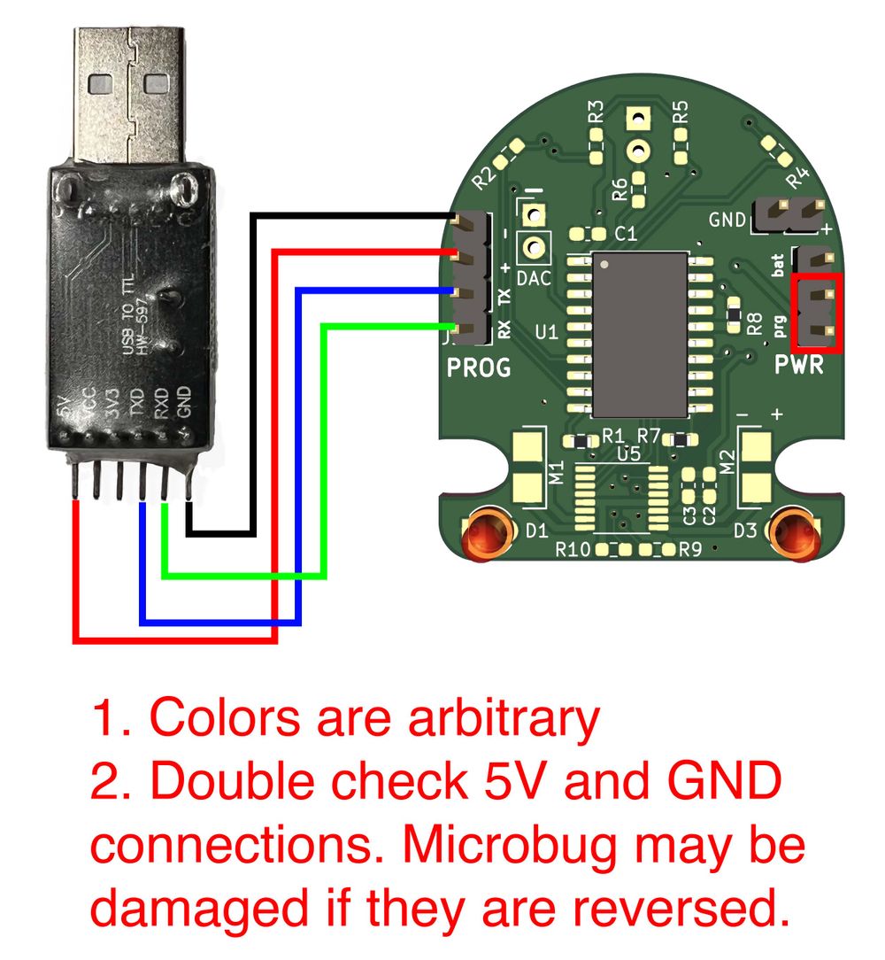
- Connect programmer to microbug: use the female to female headers to connect up the 5V to the + pin, GND to the - pin, TXD to TX and RXD to RX.
- Connect a jumper between the prg and middle pin on the power header.
- If you haven’t already, configure the Arduino IDE w/ the proper settings for the microcontroller as shown in the image from the prelab.
- First sanity test: blink LEDs (both D1 and D3)
- Take a look at the starter code and fill in the blanks to blink the LEDs in an alternating pattern (one on, other off, and vice versa) once per second. Feel free to read the Arduino reference for
digitalwrite()and look through the built-in "Blink" example (File->Examples->01.Basics->Blink). - Plug in the programmer into a USB port, and then in the IDE under Tools > Port choose the COM port:
- Upload the firmware to the board with the Upload Button:

- Your microbug's LEDs should start blinking, indicating that you can successfully upload firmware to the microcontroller.
PWM Testing
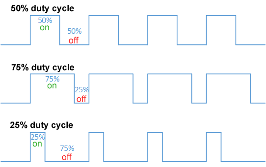
First, what is PWM? PWM stands for Pulse Width Modulation, and is a way to approximate an analog voltage with a purely digital signal. Digital signals only have 2 discrete states: HIGH and LOW (on and off, 1 and 0, etc.). However, if you flip between the HIGH and LOW states fast enough, the average output voltage over a period of time then resembles some continuous value inbetween the HIGH and LOW voltages. Subsequently, we can change this perceived average continuous value by changing the duty cycle of the HIGH-LOW oscillation. The duty cycle is the % of time in a period that the output is HIGH.
We would like you to run the prepared PWM ramp firmware to the microbug and take a look at the waveform the microcontroller generates yourself. Comment out your blinky code (or save it as another Arduino sketch file), uncomment the PWM code, and reupload the firmware to the microbug.
Using the scope to see the PWM signal:
- Set horizontal scale to 1ms/division
- Set vertical scale to 2 V/div
- Connect probe GND to GND
- Touch probe tip to physical pin 12 or 13 on the MCU. Be very careful to not short things!
Remember pins are numbered in increasing counterclockwise order, with Pin 1 at the marking dot:

Demonstrate to an instructor:
- What the PWM frequency is using the scope
- Bonus: Can you figure out what the duty cycle (and corresponding analog voltage) is for any (non-trivial) captured segment of the PWM signal?
Stage 2
Assembly
Next, you will add the reflectance sensors to your microbug and test them. You will need to first
- Solder both reflectance sensors (U2, U3) and associated passives (R2, R3, R4, R5)
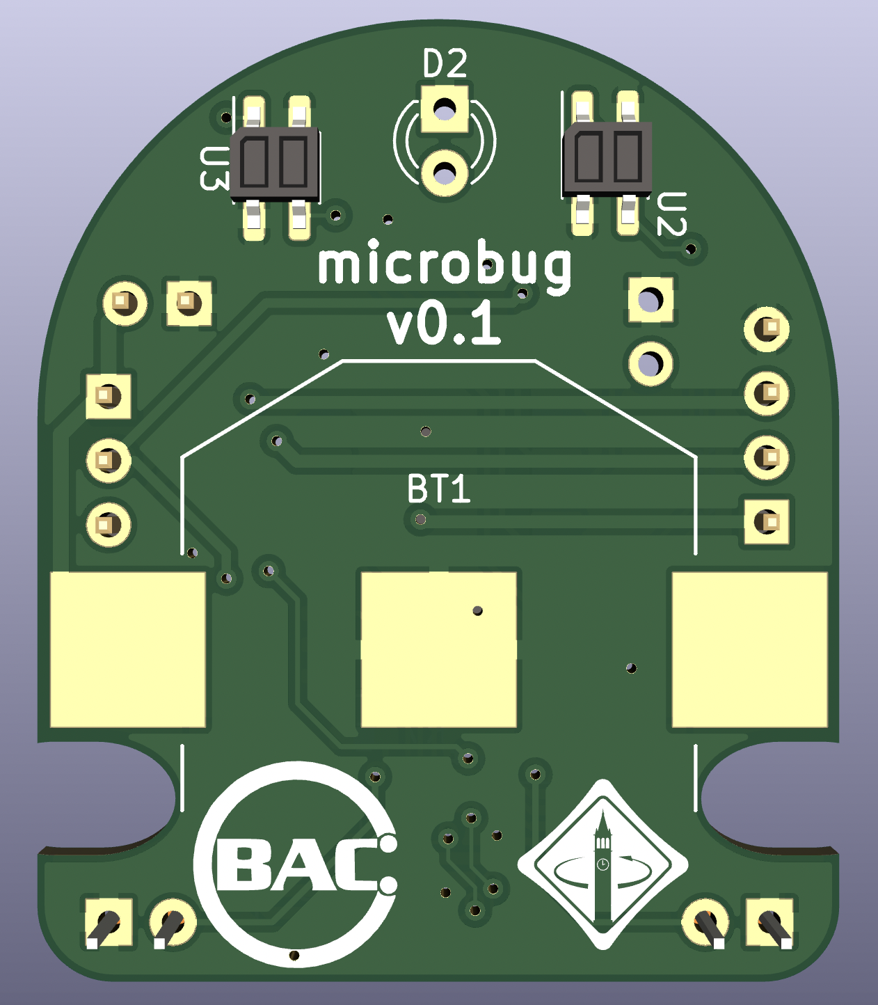
Your board should end up like so:
- Plug in the microbug to some power (either the programmer's power or the bench) and make sure you have it programmed from the previous step (otherwise the IR LED won’t be on).
- Test the reflectance sensors without micro: Use a scope to measure the voltage of the output of the phototransistor while you cover the sensor; you should see the voltage go down when you cover it.
- Test the reflectance sensors with micro (optional): Based on the voltages you saw in the previous test, we should make the LED on one side of the microbug turn on when the sensor on that side is blocked (do this for both sides). Change the lines in the test code and program your board. You may want to take a look at the documentation for
analogRead()and the example "AnalogInput" under "03.Analog" in the Examples folder. - Demonstrate your functioning reflectance sensor test to a lab instructor
Reference