


ToF Sensors
I2C
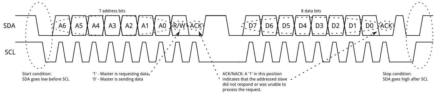
I2C (Inter-Integrated Circuit) is a popular protocol for communication between multiple leader* and multiple follower* devices using only two wires called SDA (Serial Data) and SCL (Serial Clock).
*Industry uses "master" and "slave"In our case, our Arduino is the leader device and our VL53L0X ToF sensors are follower devices. To be able to talk to multiple follower devices, we give each a different address. Communication looks a little like the following diagram. The leader device starts by sending out the desired address and then sends or receives data depending if we want to read or write.
Since I2C just provides a raw interface to send and receive bytes, what is commonly done is a register interface. Basically the first byte or two of each transaction specifies the register to read or write and future bytes are the info. Registers may contain things like sensor data or control settings such as report rate. Our VL53L0X sensors are no different. However, the sheer number of things that need to be set up is a bit much for anyone. Thankfully, someone has made a library that abstracts most of the complexity away.
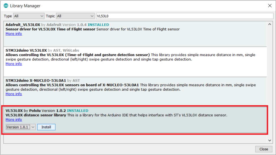
Let's install the library! If you're extra curious, check out the source code. In the Arduino IDE, open the Library Manager using "Sketch > Include Library > Manage Libraries...". Search for "VL53L0X" and download the latest version from Pololu.
The following code demonstrates how to use the VL53L0X library for one sensor. It disables the left and right sensors, sets up the center sensor, and starts printing out the distance reading from it. Please read and try to understand this code before answering the checkoff questions and moving on to the next checkoff.
Upload the code and open the Serial Monitor. Try moving your hand in front of the center sensor. The measurement isn't particularly accurate, but it's good enough for our purposes.
Checkoff #1
- Show that your center sensor is working.
- Since the ToF sensors are identical, the code above might have issues working with more than one sensor. From the perspective of I2c, what issue might we have?
I2C w/ Multiple Sensors
In I2C, each follower device must have a different address or else they might collide and break communication. Unfortunately, our identical VL53L0X sensors all start off with the same address.
Fortunately, many I2C devices come with the capability of changing their address. Usually this is done by pulling a certain pin in hardware either HIGH or LOW, but our sensor is somewhat special in that this change can be made dynamically in software with an I2C command. However, our sensors still do all start with the same address so we end up with the same problem.
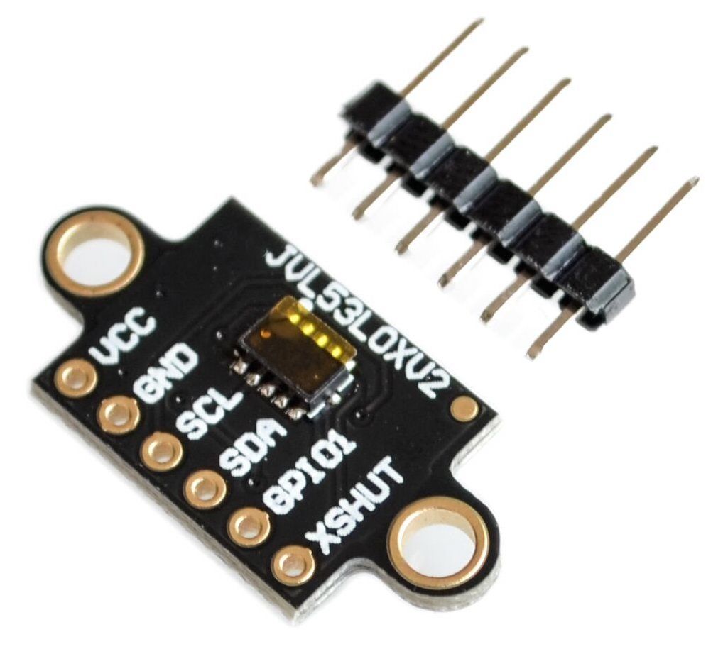
Thankfully, our VL53L0X sensors come with a reset pin (XSHUT). Most chips have a reset pin that if asserted causes the chip to ignore input and reset itself. We'll take advantage of this to give different I2C addresses to each sensor.
Here's the steps to disable a sensor whose reset pin is called XSHUT.
- pinMode(XSHUT, OUTPUT);
- digitalWrite(XSHUT, LOW); // most chips get reset when the pin is low
Here's the steps to enable the same sensor. DO NOT digitalWrite(XSHUT, HIGH)!!! Due to poor design, it is very possible to damage the VL53L0X by doing so. Instead, just use the following line.
- pinMode(XSHUT, INPUT);
Knowing the above, here's the steps to set up a different address with each sensor.
- Disable the left and right sensors (and enable the center one).
- Set the center sensor's address to 0x01.
- Enable the left sensor.
- Set the left sensor's address to 0x02.
- Enable the right sensor.
- Set the right sensor's address to 0x03.
Fill in the TODOs in the following code to set up all your sensors.
Checkoff #2
- Demonstrate all sensors working simultaneously.