


Arduino Basics
Before we can program our mice, we need to assemble them first!
Soldering Tutorial
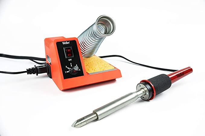
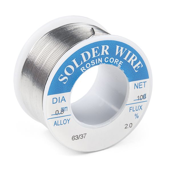
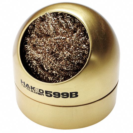
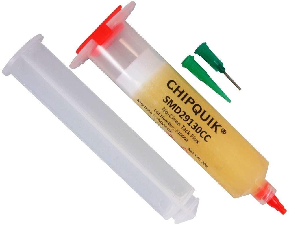
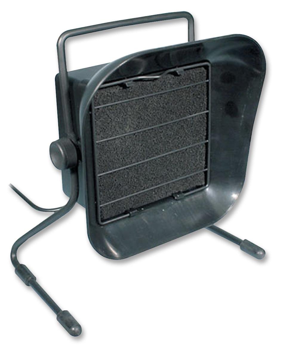
Let's start with the basics of soldering, a popular way to securely connect surfaces electrically and mechanically. Here's the minimum tools you'll need.
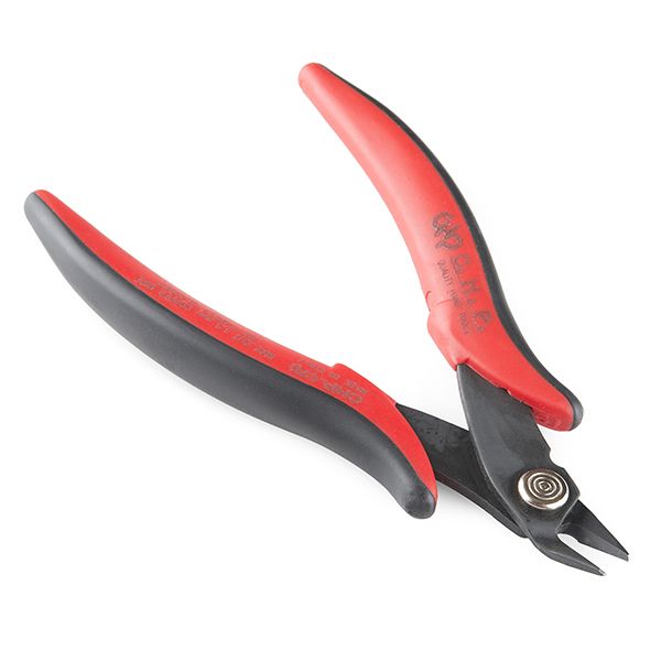
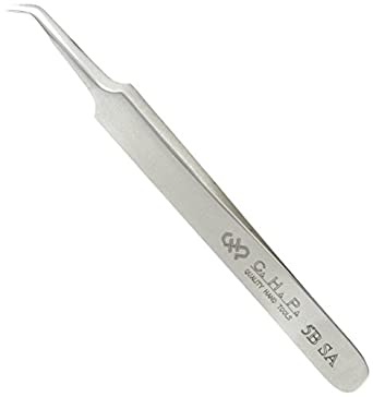
Here's a couple other tools that I personally use.
Soldering can pretty much be summed up in the following steps.
- Turn on the soldering iron and wait 1-2min for it to heat up. Remember that touching the ~700°F tip a happy camper does not make.
- Tin the iron by melting some solder on it and wipe off the excess on the brass sponge. Tinning protects the tip from oxidation and corrosion while also improving heat transfer to what you solder. Re-tin the tip every few minutes or so.
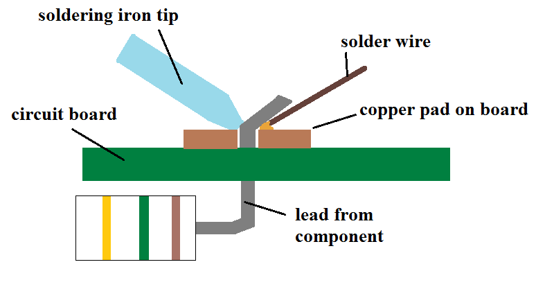
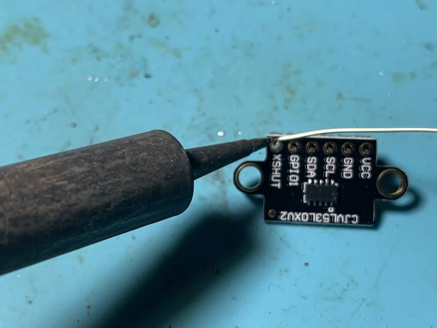
- Hold your part down so that the two surfaces you want to join are close/touching. Press the iron next to both surfaces and touch the solder to them. The solder should melt and "wet" the surfaces and cling to them. The setup looks something like the picture below.
The ideal joint will look a little bit like the following.
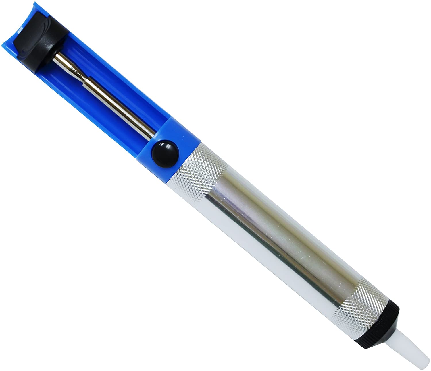
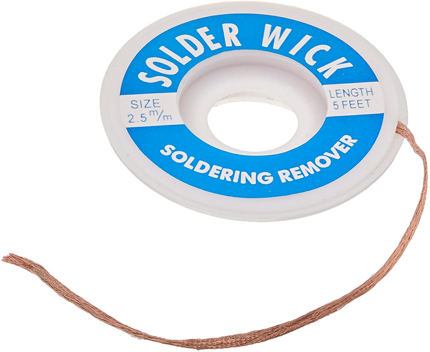
Quite a few things can go wrong when soldering, enough that Adafruit has this excellent guide of common issues and their fixes: https://learn.adafruit.com/adafruit-guide-excellent-soldering/common-problems. Generally speaking, reheating the joint will fix most of your problems. If you cause a solder bridge, ask a staff member for a solder sucker to help remove it. Soldering can take a good amount of practice to get right so don't worry if your first couple joints aren't perfect. Heck, I've been soldering for over a decade and my joints still don't look great.
PCB! Assemble.
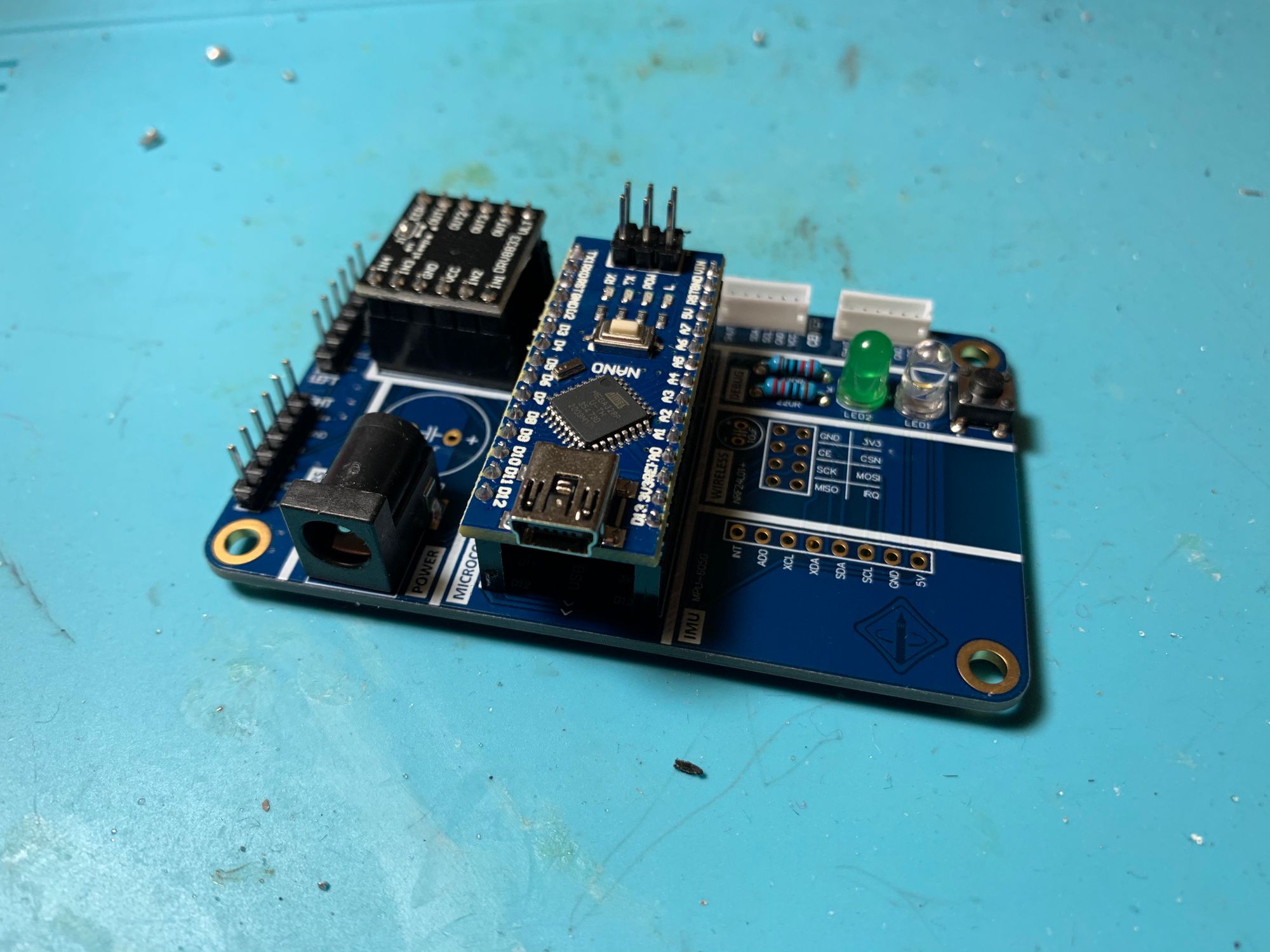
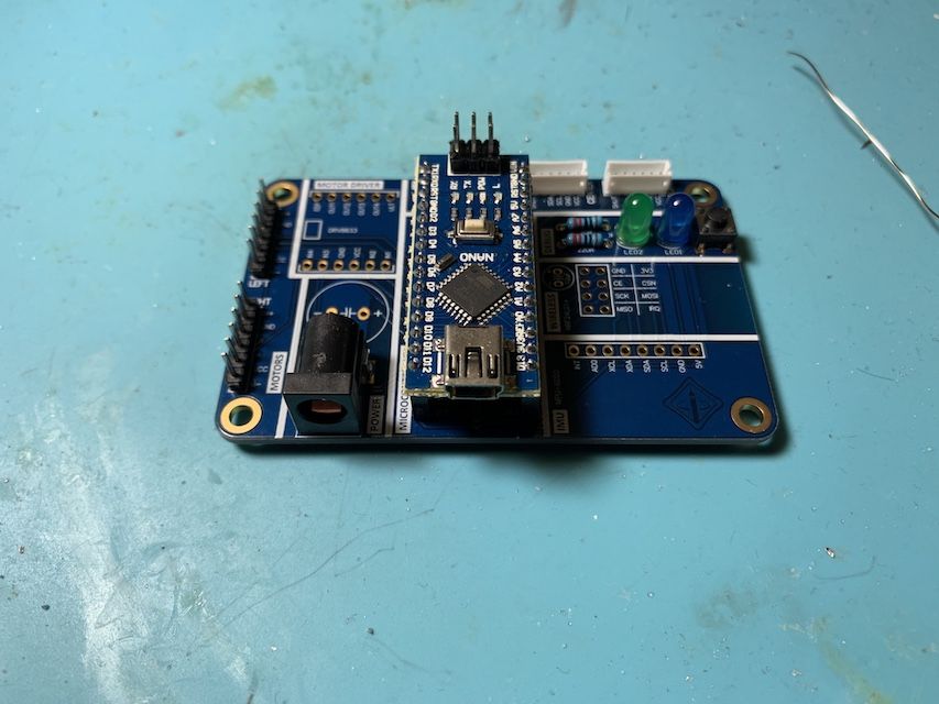
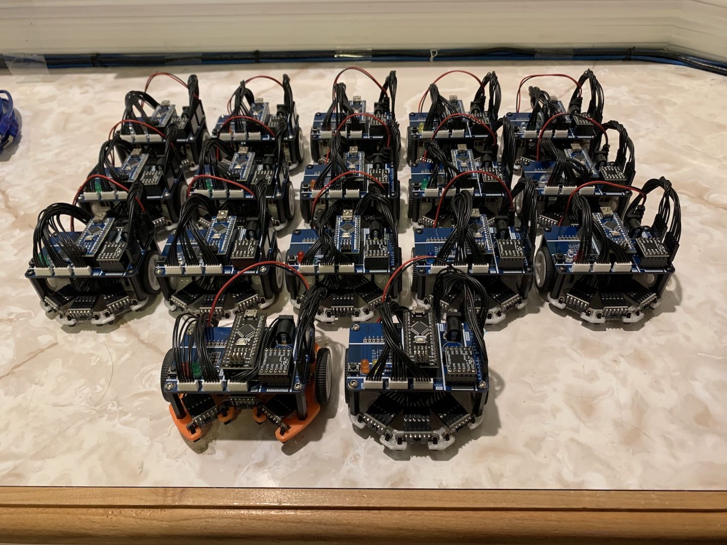
Once you're familiar with the "theory" of soldering, it's time to put it into practice! For the most part, electrical components are connected to each other with something called a PCB (Printed Circuit Board). If you want to learn how to design these yourself, IEEE has the HOPE DeCal. Anyways, your board will look like the following when you're done.
After assembling over 30 of these mice, this is the ordering of components to solder that I've found to work pretty well. Basically, solder the shortest components first. Don't worry if you don't have enough hands to hold your component in place while you solder. I usually solder one pin with the component way out of whack and then reheat the joint while pressing the component with the other hand to press the part flush against the board. Perfect alignment in two steps but only two hands. Also note that some pins take longer to heat than others because they're connected to a copper pour which acts like a huge heatsink.
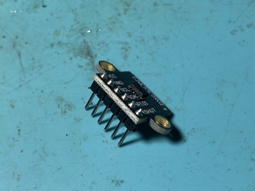
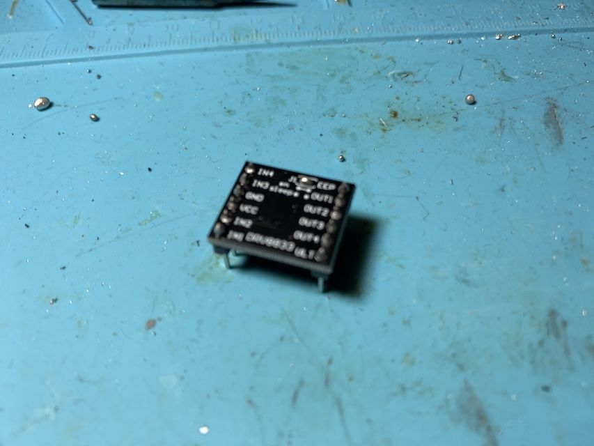
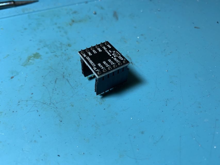
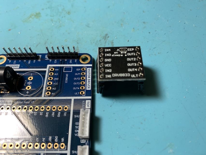
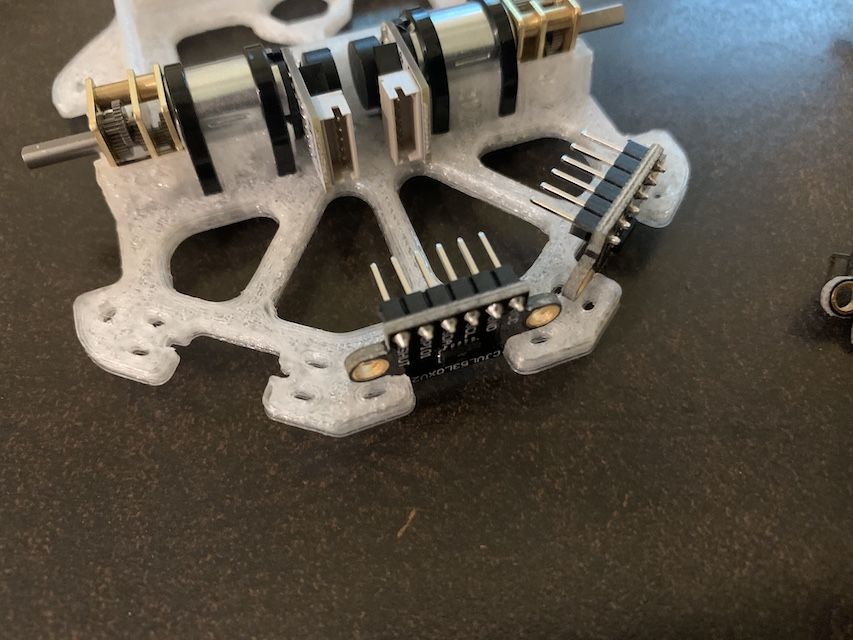
First we need to assemble three VL53L0X ToF sensor boards and one DRV8833 motor driver board. Insert the headers on the correct side and solder them down.
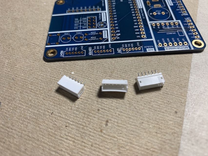
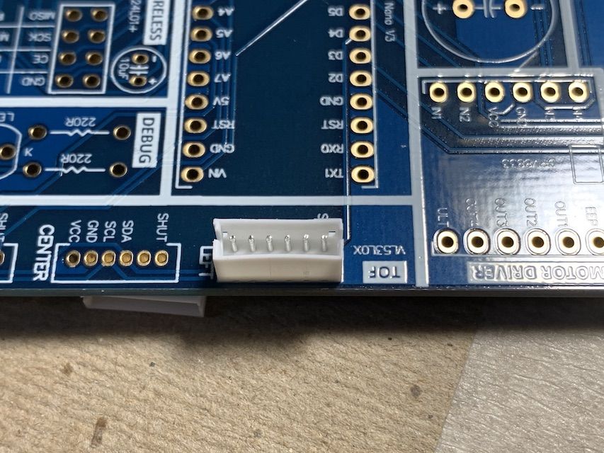
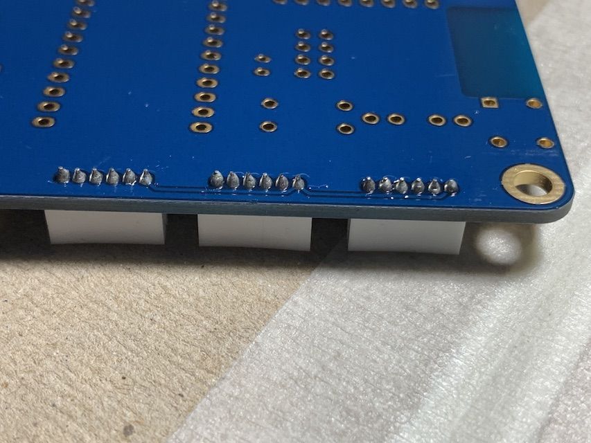
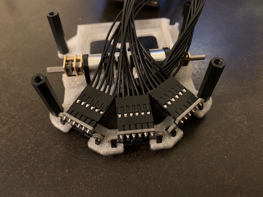
Next we move onto the Micromouse PCB, starting with the JST ZH connectors. Keep in mind the orientation. The connector should line up with the white silkscreen outline on the board. Note the pins are all quite close together so careful not to bridge pins.
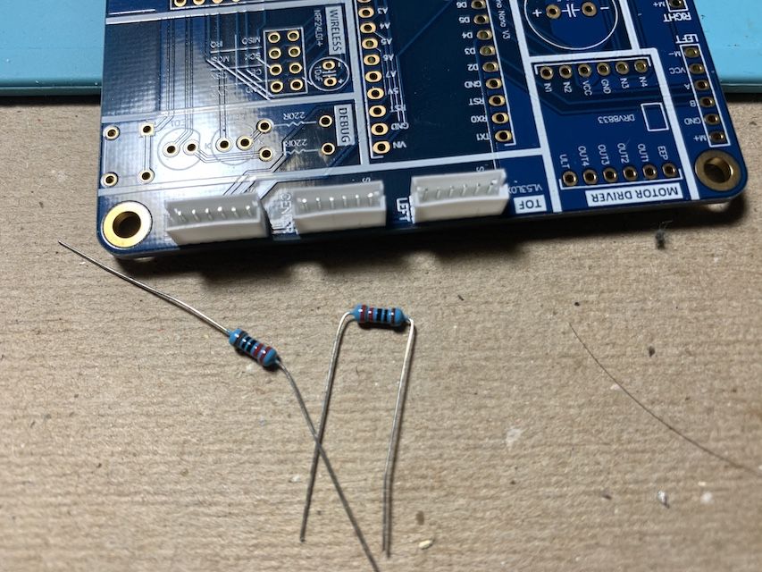
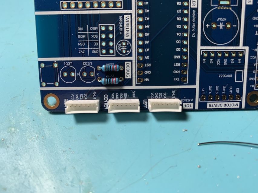
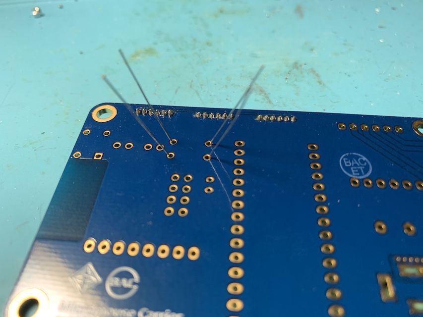
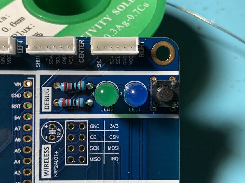
Next we solder the resistors. Bend the leads at a right angle and insert. Splaying the leads out on the other side prevents them from falling back out. Ask a staff member for flush cutters to trim the leads almost flush after soldering.
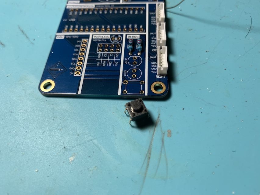
The tactile switch is a real easy one to solder due to its lead shape.
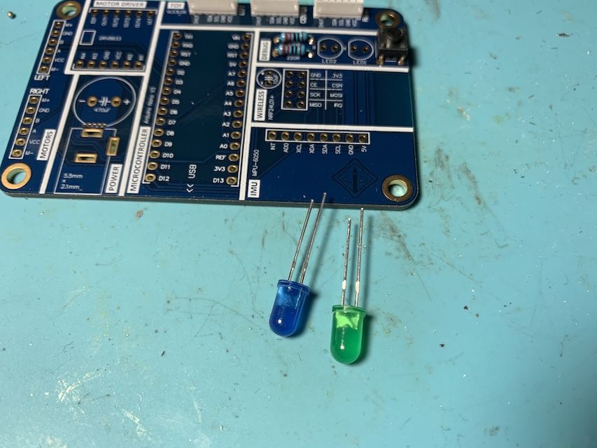
Time to add some flare. Get 2 LEDs from a staff member in the colors of your choosing. Keep in mind orientation matters for LEDs. The shorter leg should go into the hole with the flat edge on the silkscreen. If you look closely there's also a flat side on the LED bulb which is on the same side as the shorter leg.
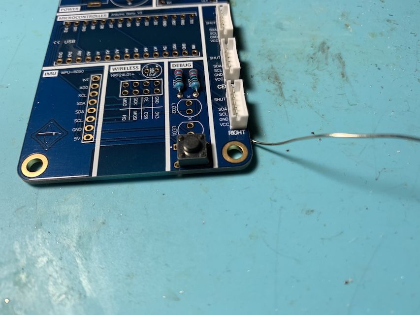
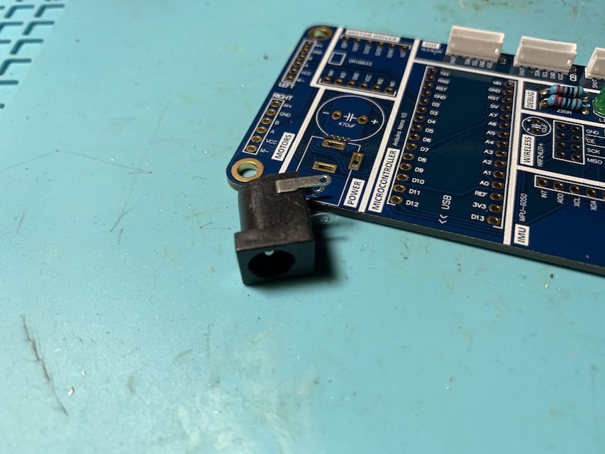
The 2.1mm barrel connector is a fun one because of its gigantic leads.
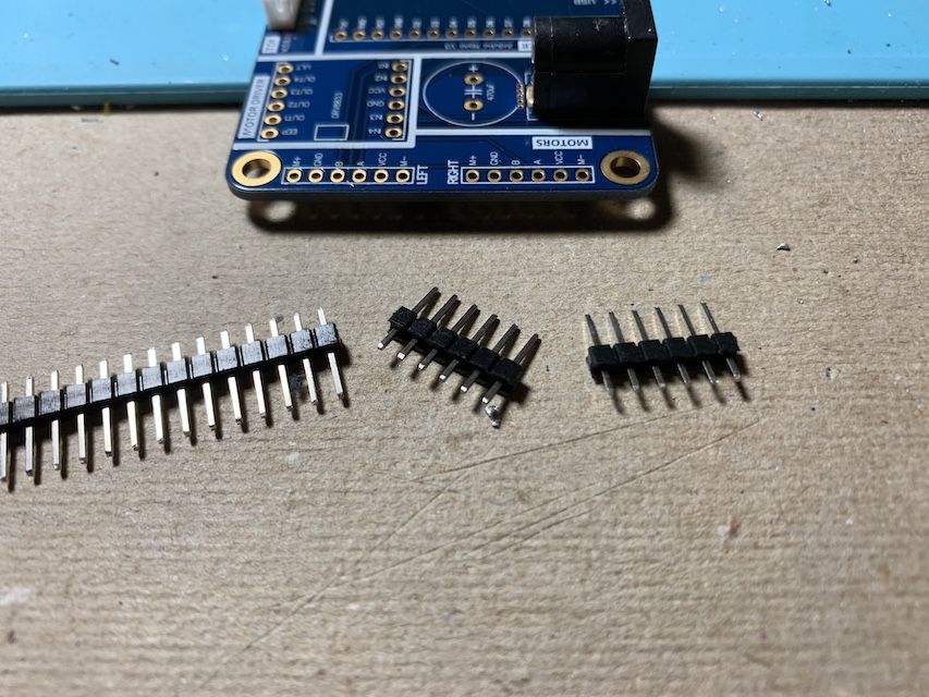
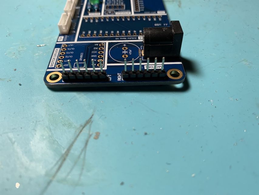
Next we solder the male headers for the motors/encoders. The header comes as a single 1x40 strip, so you'll need to break it yourself. I recommend a flush cutter. After hundreds of breaks, I just use my hands.
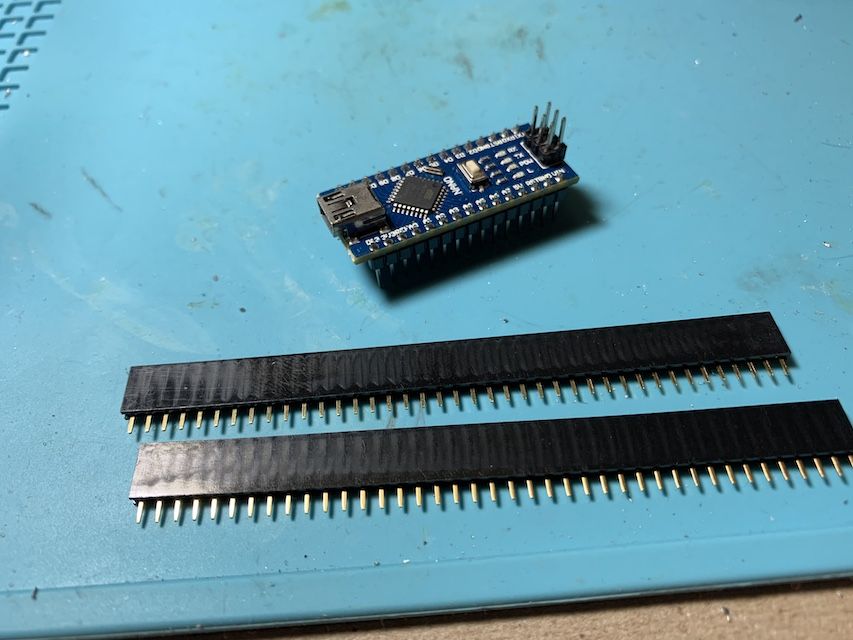
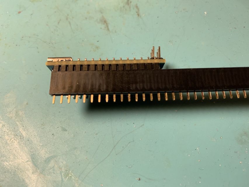
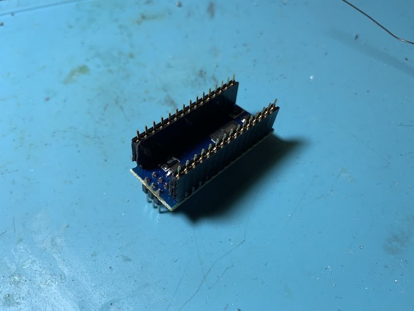
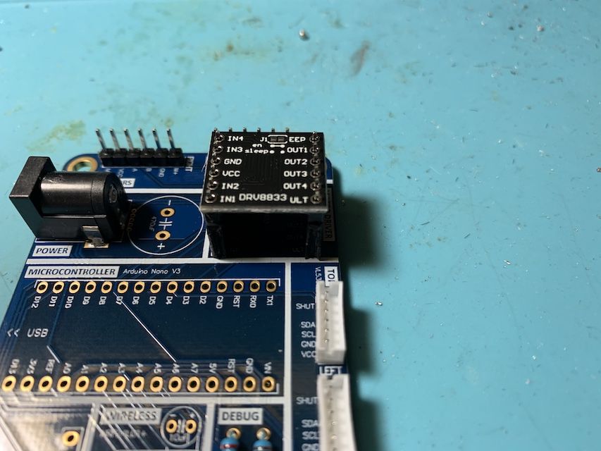
Finally, we solder the female headers for the Arduino and motor driver. This requires a flush cutter. I recommend inserting the part into the header first to know exactly where to cut. Unless you are a magical being, you must always sacrifice one pin to the cutting process. Note these parts also have a specific orientation.
Robot! Assemble.
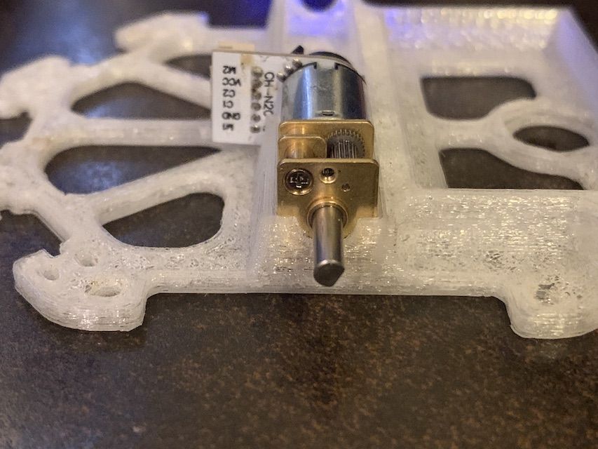
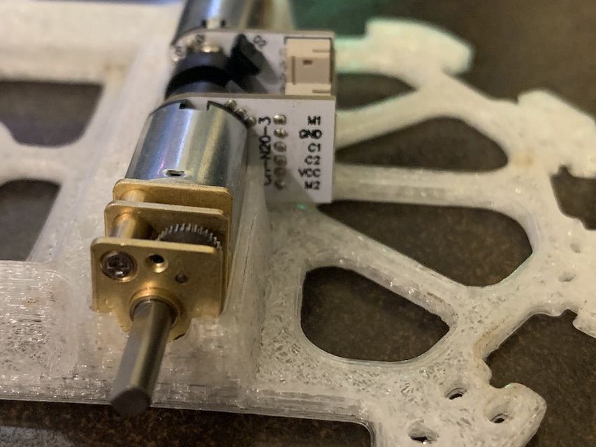
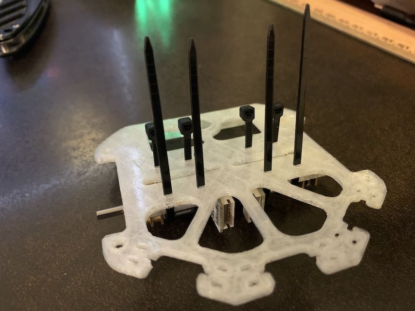
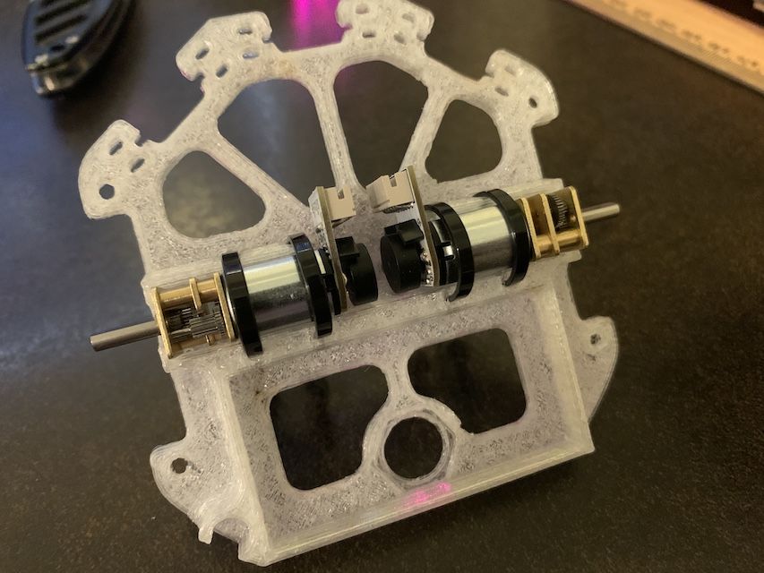
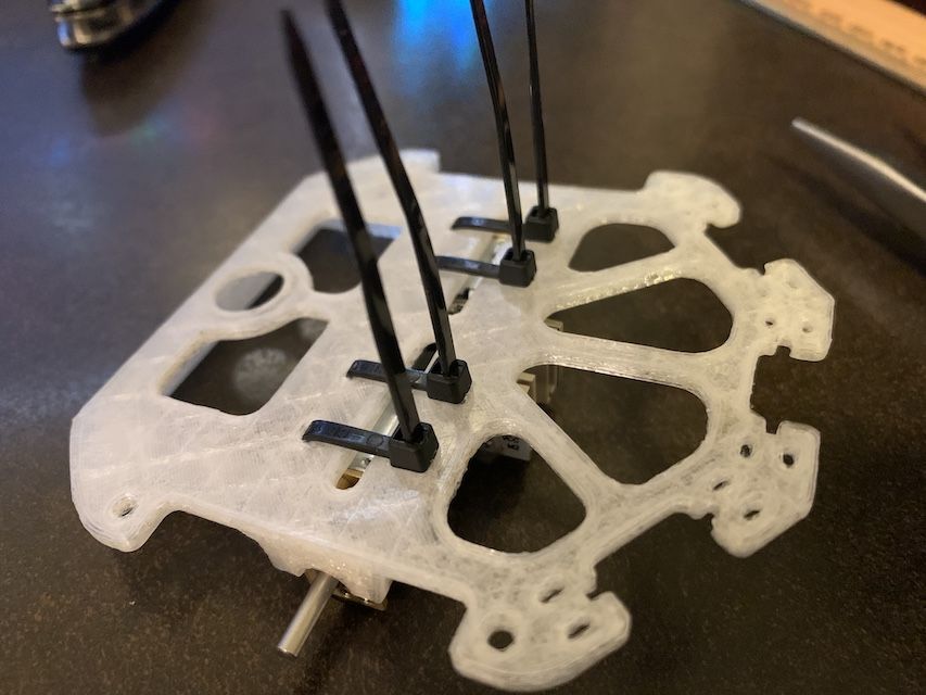
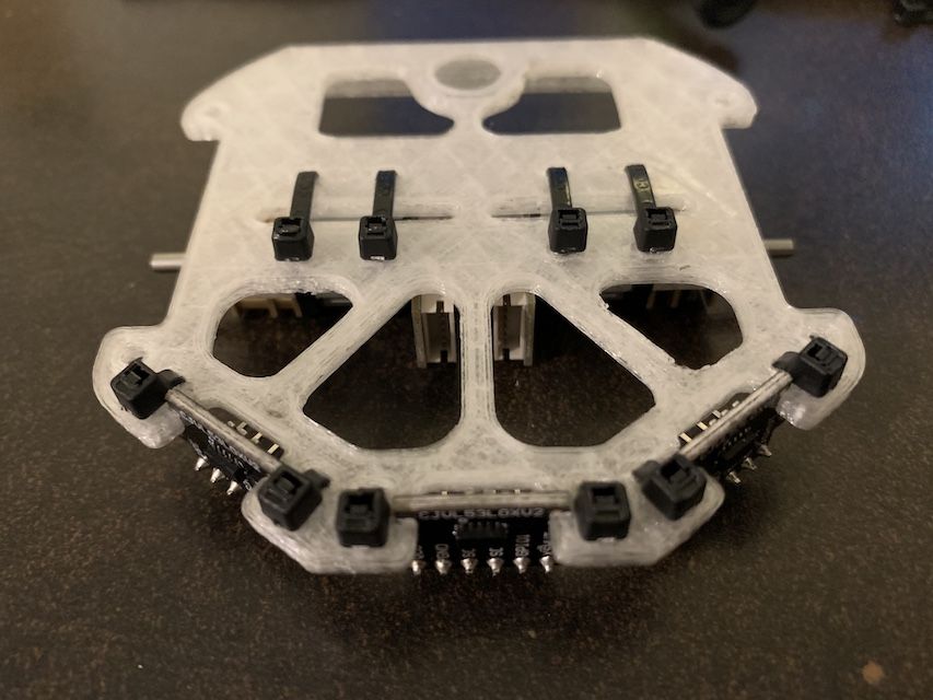
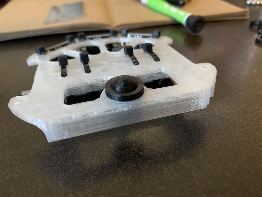
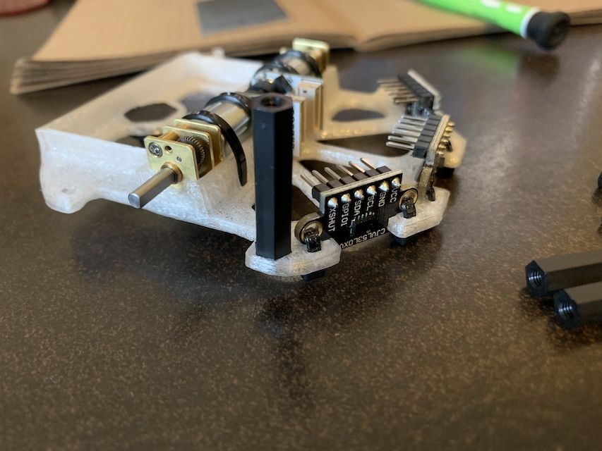
Next up is the robot chassis. Pliers are quite useful here. Let's start with the motors. Press fit both of them facing the right direction and zip tie them down.
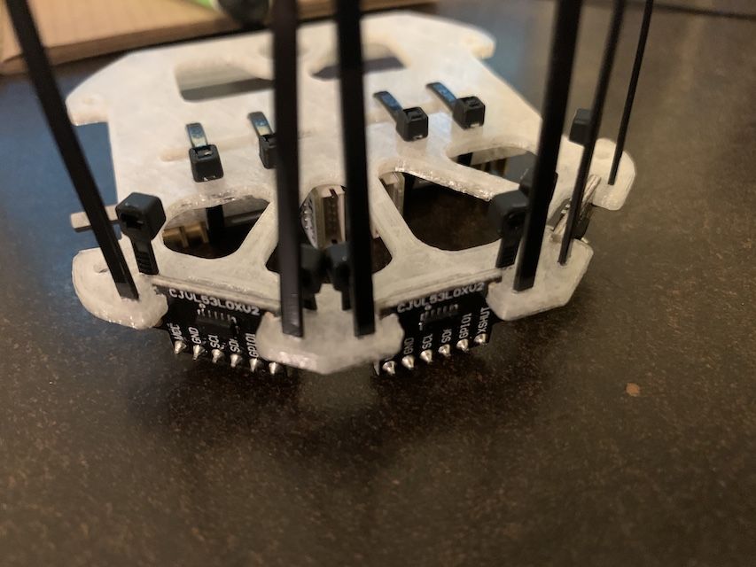
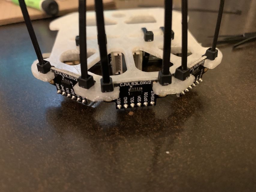
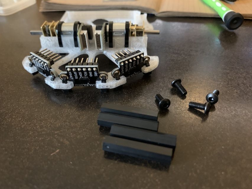
Next we mount the three ToF sensors. Again press fit and zip tie them down.
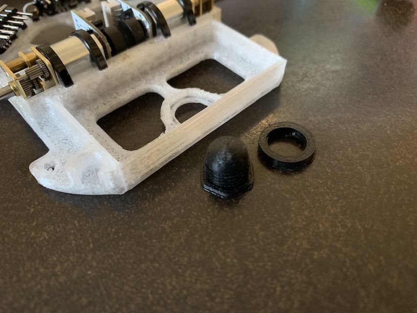
Up next is the hemisphere which is orders of magnitude cheaper than the Delrin caster we used to use but roughly 80% as effective. It keeps the robot level.
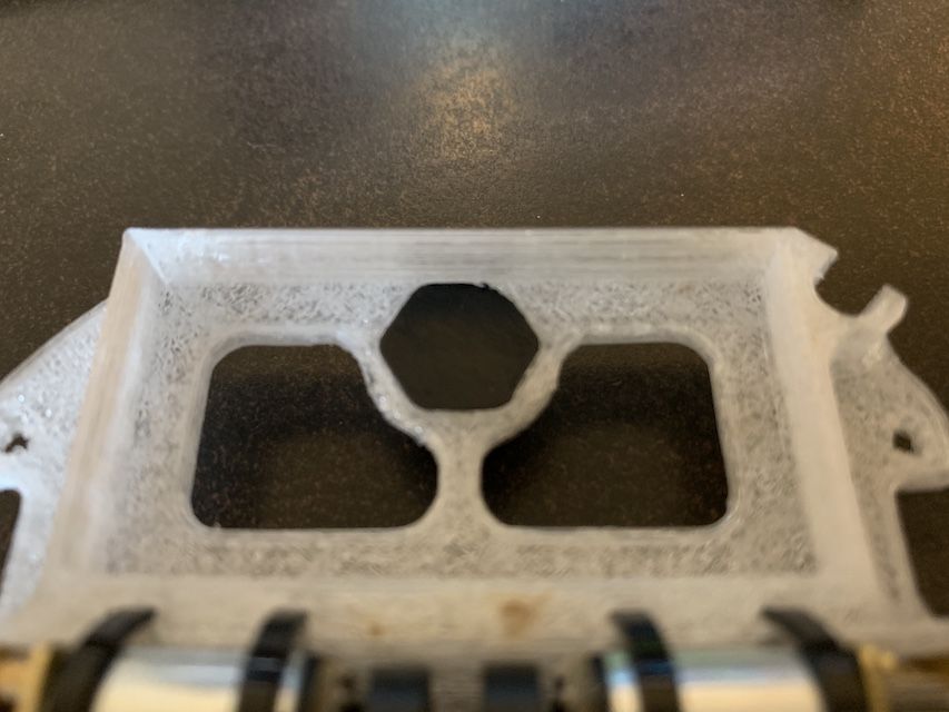
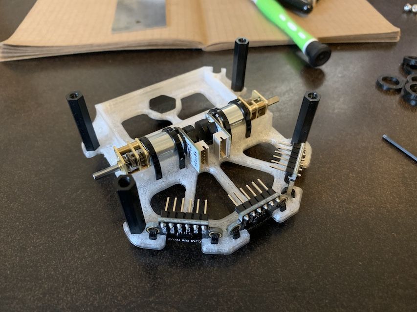
Then we mount the 4 hex standoffs. You'll need a screwdriver. Careful not to overtighten and strip the threads.
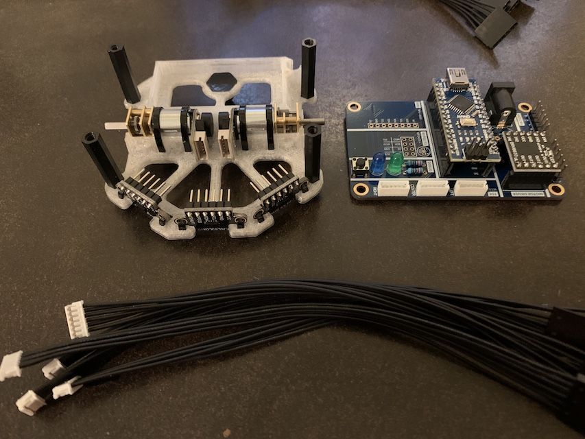
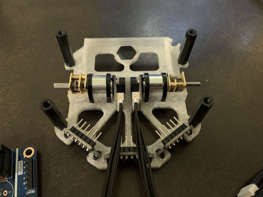
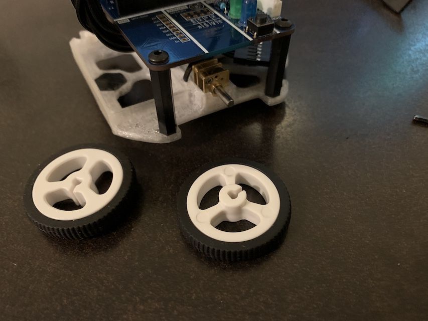
Time to put everything together. Keep in mind the cables have a polarity so take a look at the silkscreen wording on the ToF sensors and motors and Micromouse PCB to ensure correctness. If you wanna be extra fancy, twist and braid the cables together to keep things clean. Slip on the wheels and insert the battery and you're done!
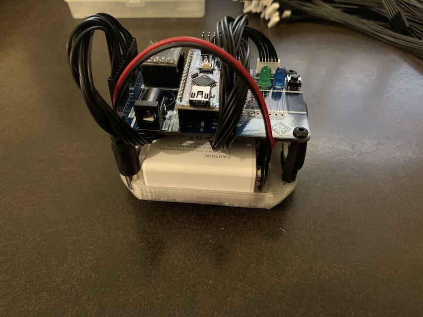
Just like that, you have a robot that'll beat E.D.I.T.H. every 1 in 14,000,605 fights. That might be an overestimate.
Checkoff #1
- Show your mentor your assembled robot!
Actual Arduino Basics
With your robot assembled, we can finally program it. Download the Arduino IDE at https://www.arduino.cc/en/software and plug in your Micromouse to your computer using the included USB cable.
- Pick your board type: Tools > Board > Arduino Uno
- Pick your COM/Serial port: Tools > Port > [correct port]
- If your COM/Serial port doesn't show up, you probably need to install CH340 drivers https://learn.sparkfun.com/tutorials/how-to-install-ch340-drivers/all.
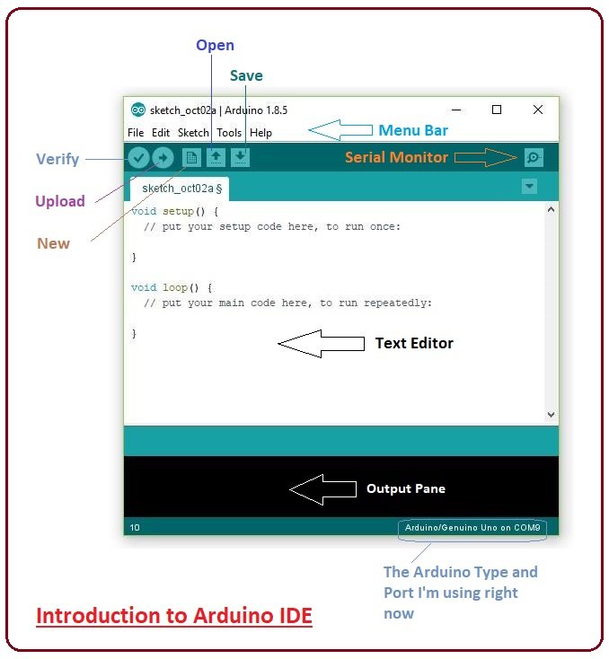
IDE Layout Overview
The main things you'll care about are the following:
- Upload button - compiles and uploads code to the Arduino
- Serial Monitor button - opens up the serial monitor for print-style debugging
- setup() function - runs once when the Arduino starts
- loop() function - runs over and over after setup()
Example 1: A New Language
The code you'll write is in C++, the most beautiful language as ranked by one director. We won't be using any of its complex features, so don't worry if you haven't coded before. Once you get used to using semicolons on every line and the whole curly brace thing, it ain't too bad. The amount of syntax we use is a lot like Java, so if you've taken CS61B you'll feel right at home.
Let's start with the blink example, the "Hello World" of embedded programming.
Paste the code into your IDE, hit upload, and bam your LED should start blinking.
Checkoff #2
- Demonstrate the blink code is working
- What is the purpose of the setup() method? When would you put code in here?
- What is the purpose of the loop() method? When would you put code in here?
Example 2: If Strikes Back
Let's take a look at a bit more syntax.
The "if" statement is something you'll see time and time again when writing code. If the conditional is true, then it runs the code inside the curly braces. We use it to decide when to turn the LED on. For more complex flows of logic, pair it up with an "else" statement or even the "else if". Even more, try out a "while" loop or a ternary operator.
Paste the code into your IDE, hit upload, and something happens... but what?
Checkoff #3
- What does counter++ do?
- After the LED turns off how long will it be until it turns back on?
- Name another conditional used in programming besides the "if" statement.
Example 3: Return of the Button
Finally, let's test out the tactile switch/button on your Micromouse PCB. Fill in the TODOs below to have your LED turn on when the button is pressed.
In practice, since the button is either pressed or not pressed we would use digitalRead() instead of analogRead() because digitalRead() returns 1 if the pin is ~5V and 0 if the pin if ~0V. analogRead() is what we use to read the analog voltage of a pin, anywhere between 0V and 5V in our case. Feel free to ask your mentor more details about the differences.
Checkoff #4
- Demonstrate your button code working