A need for a new lab
2/19
HOPE has started to run out of parts for the original "main" PCB lab, which has been referred to as the "USB Charger" lab. Last semester, when Leon went to stock up on components, he realized that a critical part had actually been discontinued! Thus a new lab needed to be created, but what?
Not-useless
We were looking for a couple of things in our new lab:
- Can work outside of a lab (looking at you USB charger)
- Not entirely useless (looking at you LED matrices)
- Integrates electrical and mechanical design features
- Could entice more micromouse students to HOPE?
During a HOPE meeting our discussion drifted to robots that zipped around. By definition they would be able to work outside of a lab, were cool to show off and educational if we could integrate its assembly with other HOPE labs, is also naturally a hard mixed domain design problem, and well, it was a micromouse.
Jeffrey decided to search up some micro motors on ebay and found these absolutely lovely tiny square motors:
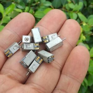
As well as this video: simple, cheap line following robot
We decided then and there this was what we were going to do.
robot basics
The robot needs to have:
- Two motors to be able to drive around freely, and appropriate motor driver circuits
- At least one light sensor and one LED
- Microcontroller should have enough I/O to take in all the inputs/control the outputs with some to spare for expansion
- ATTINY1616? Adafruit Trinket M0?
- Small, so it is cheap, but also true to the "micro" name
- Have a variety of components to solder so HOPE students get more experience
- Powered by a small battery
- Mechanically well integrated (PCB and motors and battery all fit into an enclosure)
simple? bot
2/24
We started selecting parts based on the general specifications we listed above, with one governing statistic: "swarm cost". Assuming we had a full HOPE class with 25 students, and each student successfully made one of these "microbugs", how much would the whole swarm of bots cost.
- To start, we selected a ATTiny1616 microcontroller. While larger than the ATTiny85 and other weaker variants, it offered a good deal of computing power and avaliable I/O. Programming via the Arduino environment had also been recently developed for the ATTiny 0 and 1 series, which made the whole caboodle even more attractive. It also costs less than 90 cents in (small) bulk.
- The motors had already been ordered, crazy cheap, crazy fast, crazy long shipping times from China
- To make things more exciting and expand the programming range in terms of the bot movement, we decided to include a H-bridge motor driver. At $1.10, this is the single most expensive component, but enables forwards and backwards driving of each motor individually.
- We found a super cheap and compact two-in-one LED diode and phototransistor that can be used for line sensing when facing down towards the ground, but could also be used for other things, if one so wished.
- Battery: to keep things small and cheap, we went with a CR2032 coin battery. Priority to the price, not spec. The PCB solderable battery holder was also considered.
simple table of parts
| Part(s) | Price |
|---|---|
| Micro(Attiny1616) | $0.83 |
| motors(2) | $0.54 |
| battery(CR2032) | $0.27 |
| battery holder | $0.65 |
| motor driver | $1.10 |
| light sensor(2) | $1.34 |
| LED | $0.00 |
| PCB | $0.00 |
| Total | $4.73 |
| Swarm Size | 25 |
| Swarm Cost | $118.15 |
| # boba equivalent | ~30 |
quick schematic and layout
thank you Jeffrey for being an absolute speed demon
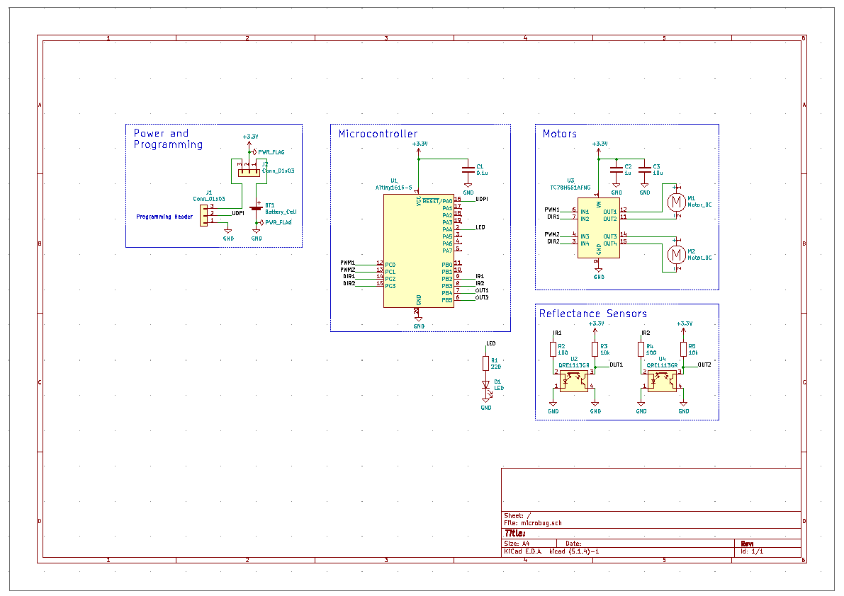
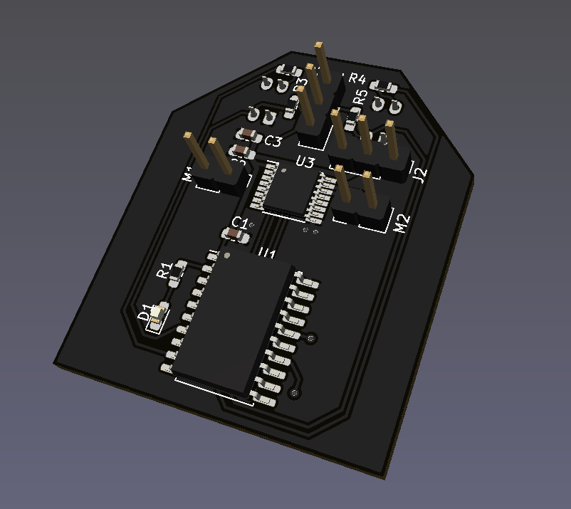
The finalized layout will definitely be bit more accessible to solder, nicely silkscreened, etc. But the sizing is something we plan to keep approximately: 1 by 1.5in. The final board will not be any bigger than this.
a couple of other things
To keep the board expandable for future students who may want it to do even crazier things than we can think of, we plan on designing the layout and mechanical for
- additional footprints for other components, such as an IMU
- variable size footprints for passives, for soldering practice as well as to act as informal testpoints
- future battery expansion to lipo
hardware prototype
Before making a PCB, it is generally a very good idea to prototype your circuit and make sure the most important parts work as intended. In our case, we made a quick breadboard then perfboard mockup of the entire robot.
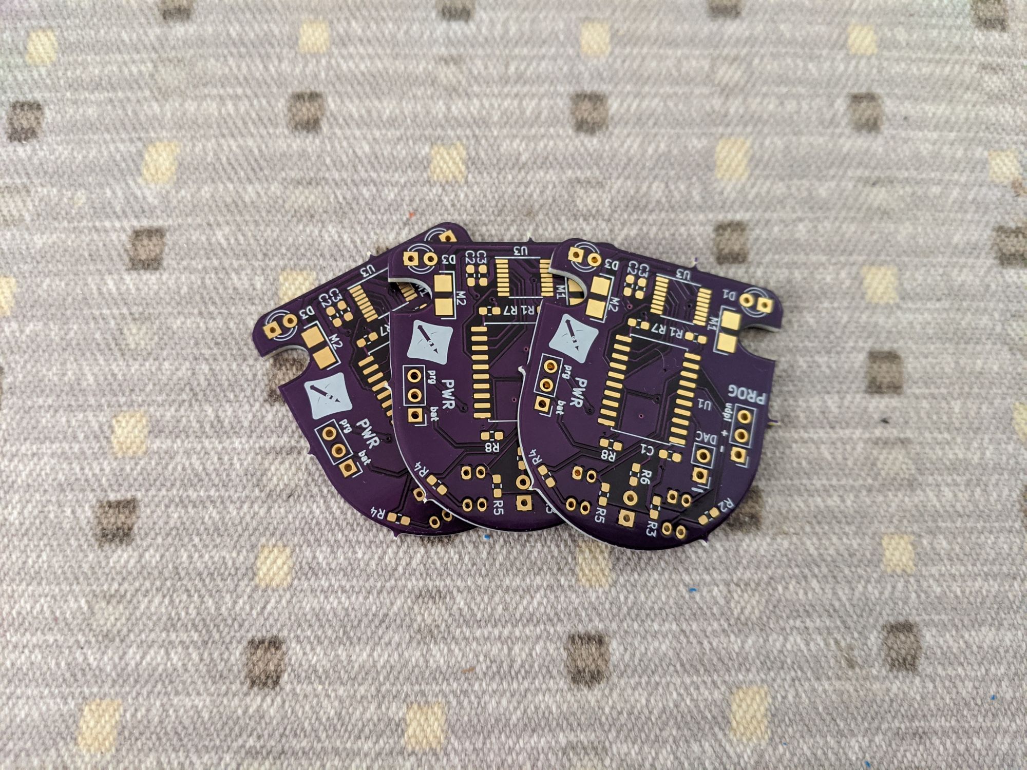
manufactured board...