


In-Lab
Assembly
We'll be soldering a few more components on to the Microbug:
- Solder motor driver IC (U5)
- Solder motor driver resistors (R9, R10)
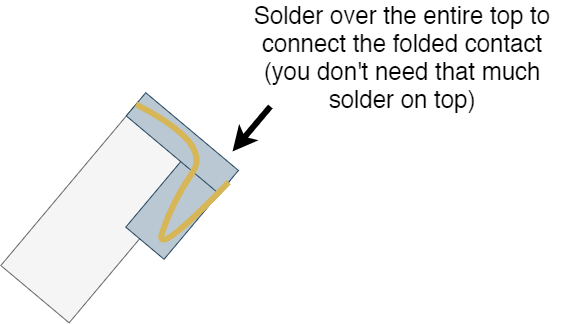
- Solder motors (M1, M2): use may want to use our 3D printed jigs to help you hold the motor in place as you solder the contacts. We recommend soldering all the way up the contact on the motor to the back of the motor for increased structural stability. The contact is actually a folded piece of metal that could potentially unfold and break.
Before soldering your motors, due to manufacturing variance, the cheapness of these motors, and some unintended modifications we did to the motors, not all of them actually work. We have already pre-tested all the motors we bought and you should only be getting the functioning ones, but a second test is always good. We don’t want you to have to desolder and resolder motors since they can be a little annoying to solder. Set the power supply to 3V (and set a current limit of ~100mA) and apply power across the motor terminals in any polarity and make sure both motors spin.
- HOT GLUE YOUR MOTORS IN PLACE BEFORE SOLDERING THE BATTERY HOLDER
- Solder battery holder
Before soldering the holder down, put a small amount of solder on the exposed center pad! If you don’t do this the flat negative terminal of the battery will likely be unable to make good contact.
The only parts missing now should be C1, C2, and C, which are decoupling caps.
Upload this simple on-off test code for the motors which should turn on the motors on the same side as the LED. Due to some unforeseen and unexplainable issues with the motor driver we have chosen, the motors don’t actually spin when the device is powered by 5V. After programming, change the power source from the programmer from the 5V to the 3.3V pin. You should see the LEDs blink and the motors turn.
If you need the starter code again, you can find it here: https://github.com/IEEEBerkeley/microbug_fw
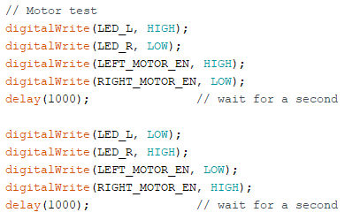
digitalWrite(LED_L, HIGH);
digitalWrite(LED_R, LOW);
digitalWrite(LEFT_MOTOR_EN, HIGH);
digitalWrite(RIGHT_MOTOR_EN, LOW);
delay(1000);               // wait for a second

digitalWrite(LED_L, LOW);
digitalWrite(LED_R, HIGH);
digitalWrite(LEFT_MOTOR_EN, LOW);
digitalWrite(RIGHT_MOTOR_EN, HIGH);
delay(1000);               // wait for a second
Decoupling Caps
Now we can do a simple experiment to show the importance of decoupling capacitors. Motors generate lots of noise on power lines (they can draw lots of current, and the amount of current can vary wildly and randomly) along with all the digital logic switching, and this can prevent the microcontroller from properly operating. You’ll see that when you use the programmer to power the microbug, there seems to be no problem. Hook up the microbug up to the power supplies using the long test leads and see if it works now. We’ll do some measurements to see what is going on.
- Use the code above to drive motor IC
- Power the microbug with a benchtop power supply
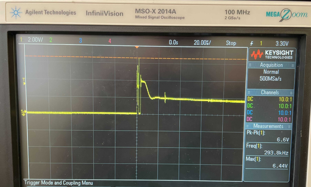
- Capture a scope shot of 3.3 V rail near the driver as it starts to draw current (trigger)
a. Set the trigger level to 3.5 V (trigger menu)
b. Set the horizontal scale to 20 us/div
c. Set the vertical scale to 2 V/div
d. Power the board
e. Probe the 3.3 V rail on either C2 or C3
f. Arm the trigger by pressing the Single button. This will immediately cause a capture on the scopes we have in lab (this is not typical for scopes in general!), so you’ll need to press it again to capture the single of interest.
g. Take a picture of the waveform, and note the peak voltage
Now solder decoupling capacitors (C1, C3, C2) and repeat:
- Capture a scope shot of 3.3V rail near the driver as it starts to draw current (trigger)
Finishing Assembly
- Solder a small LED to the front (D2) to act as the caster
- Solder R6
System test
If you want to try to get your microbug to follow lines, you can try writing your own code or we can give you some code to follow a line. Our implementation is very simple and doesn't work well but can be a starting point for more complex control methods. From here on out you can ask us for a coin cell to drive the robot untethered (although the runtime may be relatively short due to the cell's very limited capacity; you can attach something like a small LiPo to the top side power header on your own time if you want extended run times).
Turns out, there's a lot more testing that should be done if you want an end product that works well. You may experience issues like this for your projects as well, unless you prepared very well.